www.balluff.com 17english
6
Calibration procedure
The BTL can be programmed with a calibration device (see
Section 6.1) or with the calibration box (see
Programming inputs).
6.1 Calibration device
The calibration device (see Accessories on page29) is
an additional device for calibrating the BTL.
Use calibration device
DANGER
Explosions
Opening the housing can result in sparks which can trigger
explosions in explosive atmospheres.
► Do not open housing when an explosive atmosphere
may be present!
Automatic deactivation!
If the buttons on the calibration device are not
pressed for approx.10min,
programming mode is automatically ended.
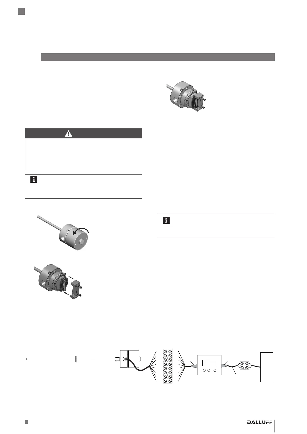
1. Unscrew and remove housing cover.
2. Slide calibration device into place.
3. Program BTL (see Sections 6 to 9).
4. Remove calibration device.
5. Re-install the housing cover flush and tighten to
33…40Nm (25…30ft∙lb). Tighten secondary retaining
screws (ATEX).
6.2 Programming inputs
Instead of the calibration device, the programming inputs
may also be used for setup:
– La corresponds to the blue button
– Lb corresponds to the gray button
– A programming input at 10 to 30V corresponds to
activation (high active).
The Balluff BTL7-A-CB02-K calibration box can be used
for this (see Accessories on page29).
Automatic deactivation!
If no signals are transmitted via the
programming inputs for approx.10min,
programming mode is automatically ended.
YE
GY
PK
RD
GN
BU
BN
WH
YE
GY
PK
RD
GN
BU
BN
WH
Fig. 6-1: Connecting the BTL7-A-CB02-K calibration box
BTL
Calibration box
Supply
8-port luster terminal
Adapter cable with
connector (luster
terminal)
6-pin
8-pin
BTL7-A/C/E/G5_ _-M_ _ _ _-J-DEXC-TA12
Magnetostrictive Linear Position Sensor – Rod Style
Type of protection “db” and “ta”
Flameproof enclosure