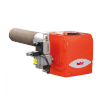
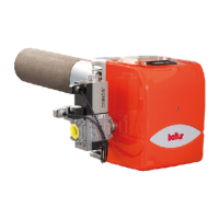
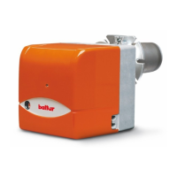
BURNER CONNECTION TO THE BOILER
Insert the burner head (1) into the furnace
Be very careful not to damage the ceramic of electrodes (2; 3), since
a microcrack would cause boiler malfunctions.
Proceed by locking the ange (6) to the boiler door
inserting the gaskets (4 ; 5) and tightening the nuts (7) into the stud
bolts (8)
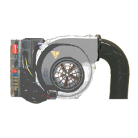
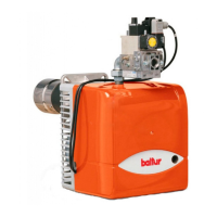
GAS TRAIN
GAS TRAIN DESCRIPTION FOR GAS PRESSURE ADJUSTMENT
The burners are combined with monobloc pneumatic proportional gas
valves that allow the quantity of gas supplied and therefore the power
output, to be adjusted.
A pressure signal, detected in the air circuit, is sent to the pneumatic
gas valve, which delivers a quantity of gas proportional to the airow
processed by the fan.
1
2
8
4
5
6
7
0002950260
3
(gas/air)
Air inlet
Gas inlet
BPM90_800_valvola_venturi
ENGLISH
13 / 40
0006160310_202001