ELECTRICAL CONNECTIONS
The burner can be installed exclusively in environments with pollution
degree 2 as specied in Annex M of Standard EN60335-1:2008-07.
The monophase power supply line must have a switch with fuses.
For the electrical connections (line and thermostats), follow the enclo-
sed wiring diagram.
To carry out the connection of the burner to the power supply line
proceed as follows:
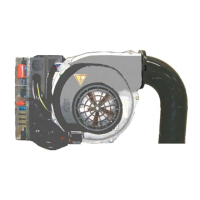
Unscrew the screw (1) and remove the lid (2) to access the burner's
electrical panel.
Connect the 7-pin plug (4) and the 3-pin plug (3) to the corresponding
sockets (5) and (6).
Close the cover (2) and lock it with the screw (1).
CAUTION / WARNINGS
The housings for the cables for the 7 and 4 pole plugs are for
Ø 9.5-10 mm and Ø 8.5 - 9 mm cable respectively, this is to
ensure the protection rating of IP 44 (Standard IEC EN 60529).
CAUTION / WARNINGS
Only professionally qualied personnel may open the burner
electrical switchboard.
CAUTION / WARNINGS
Before performing maintenance works disconnect the power
supply and make sure it cannot be re-connected by accident.
5
CollEle_BPM01
4
3
1
2
ENGLISH
17 / 40
0006160310_202001