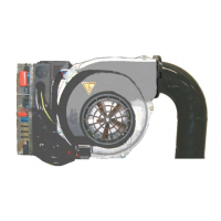
GAS TRAIN DESCRIPTION FOR GAS PRESSURE ADJUSTMENT
BPM 10 - 40 - 90
1 Gas solenoid valve
2 Maximum pressure adjustment screw (rotate counter-clockwise to
increase and clockwise to decrease)
3 Minimum pressure adjustment screw (counterclockwise to increa-
se, clockwise to decrease)
4 Gas inlet
5 Gas inlet pressure port
6 Gas outlet pressure valve
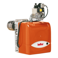
BPM 140
1 Gas solenoid valve
2 Maximum pressure adjustment screw (rotate counter-clockwise to
increase and clockwise to decrease)
3 Minimum pressure adjustment screw (counterclockwise to increa-
se, clockwise to decrease)
4 Gas inlet
5 Gas inlet pressure port
6 Gas outlet pressure valve
DANGER / ATTENTION
The adjustment screw (2) does not have a stop position, so a
further turn will cause it to start opening the valve when this is
completely closed.
4
1
3
5
A
2
BPM_BPMO90_rampa_gas
6
3
A
4
6
5
1
BPM_90_800_011
2
RegValv_BPM_140
ENGLISH
14 / 40
0006160310_202001