HB-0502-03
15
INSTALLATION
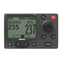
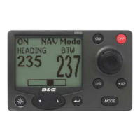
The display heads are supplied with a clip-in mounting
bracket which allows for easy installation, access from
behind is not necessary to secure the unit in place. However
to prevent theft and permanently fix the unit in position,
locking studs and thumb nuts are supplied.
SITING THE UNIT
All Network Instruments are designed for mounting on or
below deck. A mounting position should be selected where
they are:
• Easy to read by the helmsman
• On a smooth and flat surface
• At least 100mm (4") from a compass
• Accessible from behind for fitting locking studs if
required.
MOUNTING THE UNIT
Use the cutting template supplied to mark the centres of the
holes for the self-tapping screw, the fixing stud holes and the
mounting bracket.
• The template allows 4mm (5/32") between adjacent
units for the suncover, increase this distance if required to
maximum of 60mm (2 3/8") between units or 180mm
(3 1/8") between centres. For greater distances between
units extension cables are available.
• Use a 70mm (2 3/4") diameter hole-cutter for the
mounting bracket hole.
• Use a 2.9mm for the self-tapping screw holes.
• Use a 5mm (3/32") drill for the locking stud holes.
• Secure the mounting bracket to the bulkhead with the
self-tapping screws supplied
• Fit the rubber sealing gasket around the mounting
bracket.
• Screw the locking studs into the back of the display
head (if required).
• Carefully pass the cable tails through the mounting
bracket hole, connect the cables to the main units.
• Clip the display head into the mounting bracket.
• Secure the instrument with the thumb nuts supplied.