Bandit39
MODEL 75 MAINTENANCE
Main Drive Belts: Refer to “Belt Tension Table”
Pump Drive Belts: 1/4” (6.4 mm) deection with
9 lbs. (4.1 kg) of force.
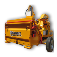
BELT
SHEAVE
WORN BELT
BELT
SPACE
GOOD BELT
SHEAVE
BELT
SHEAVE
WORN SHEAVE
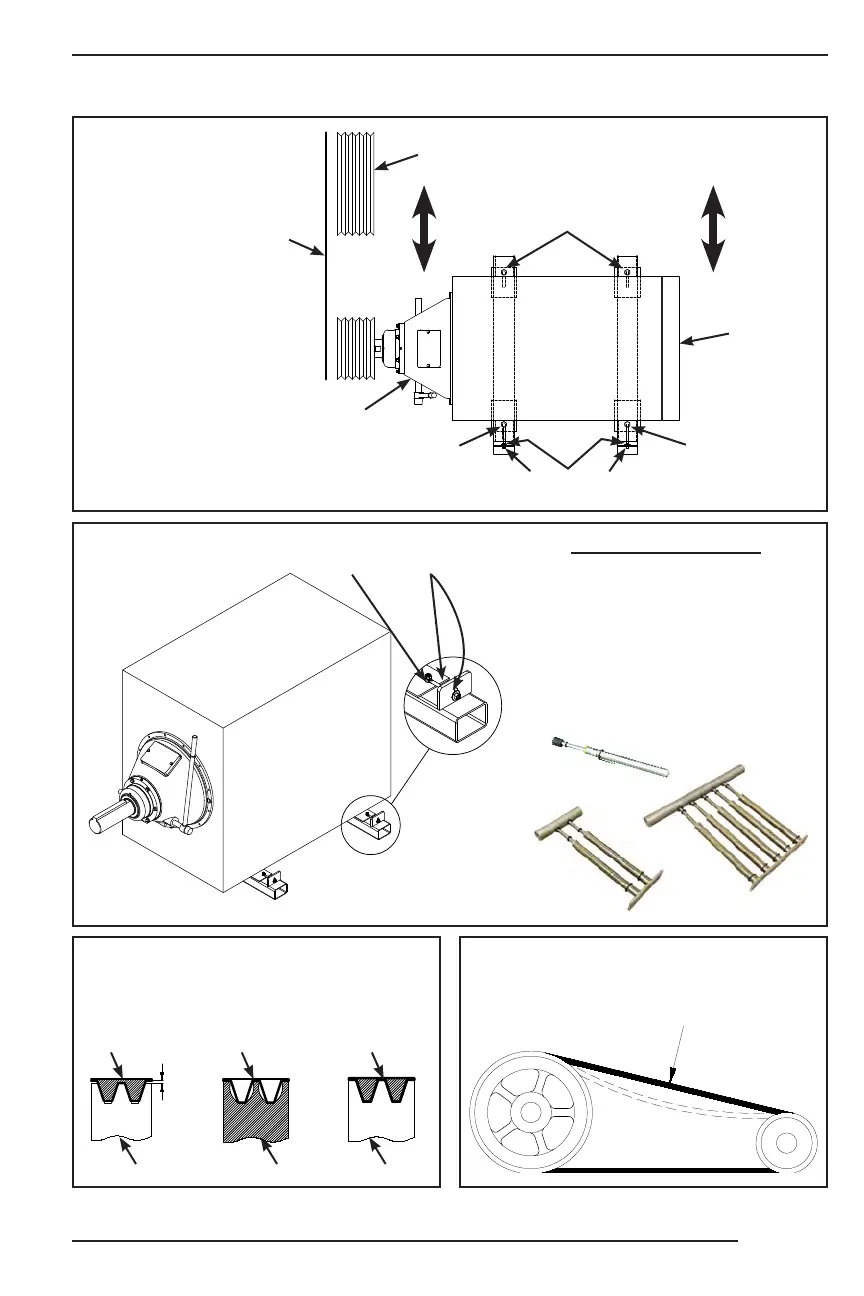
Worn or misaligned belts and sheaves in the power train
causes belt slippage, thus power loss. Keep the power
train working for you, not against you, by checking for
needed adjustment or replacement.
BELT TENSION
FIGURE 1
POSITIONING
JAM NUTS
CLUTCH END
OF ENGINE
CHIPPER
SHEAVE
ENGINE MOUNTING
BOLTS
ENGINE
SHEAVE
CHECK SHEAVE
ALIGNMENT WITH
STRAIGHT EDGE
OR STRING
RADIATOR
END OF
ENGINE
ENGINE
MOUNTING
BOLT
ENGINE
MOUNTING
BOLT
FIGURE 2
BELT TENSION GAUGES
SINGLE BARREL GAUGE
(UP TO 30 lbs.) 900-1919-23
DOUBLE BARREL GAUGE
(UP TO 66 lbs.) 900-1917-02
TRIPLE BARREL GAUGE
(UP TO 90 lbs.) 900-1919-67
FIVE BARREL GAUGE
(UP TO 165 lbs.) 900-1919-66
ENGINE
ADJUSTER
POSITIONING
JAM NUTS