Bandit73
MODEL 75 REPLACEMENT PARTS
* Hydraulic components, ttings, hoses will vary depending on
optional equipment. Order by physical description.
** Hydraulic pumps need to be ordered by physical description and serial number of machine.
Make sure to order components according to tting
type, ttings may vary on all components.
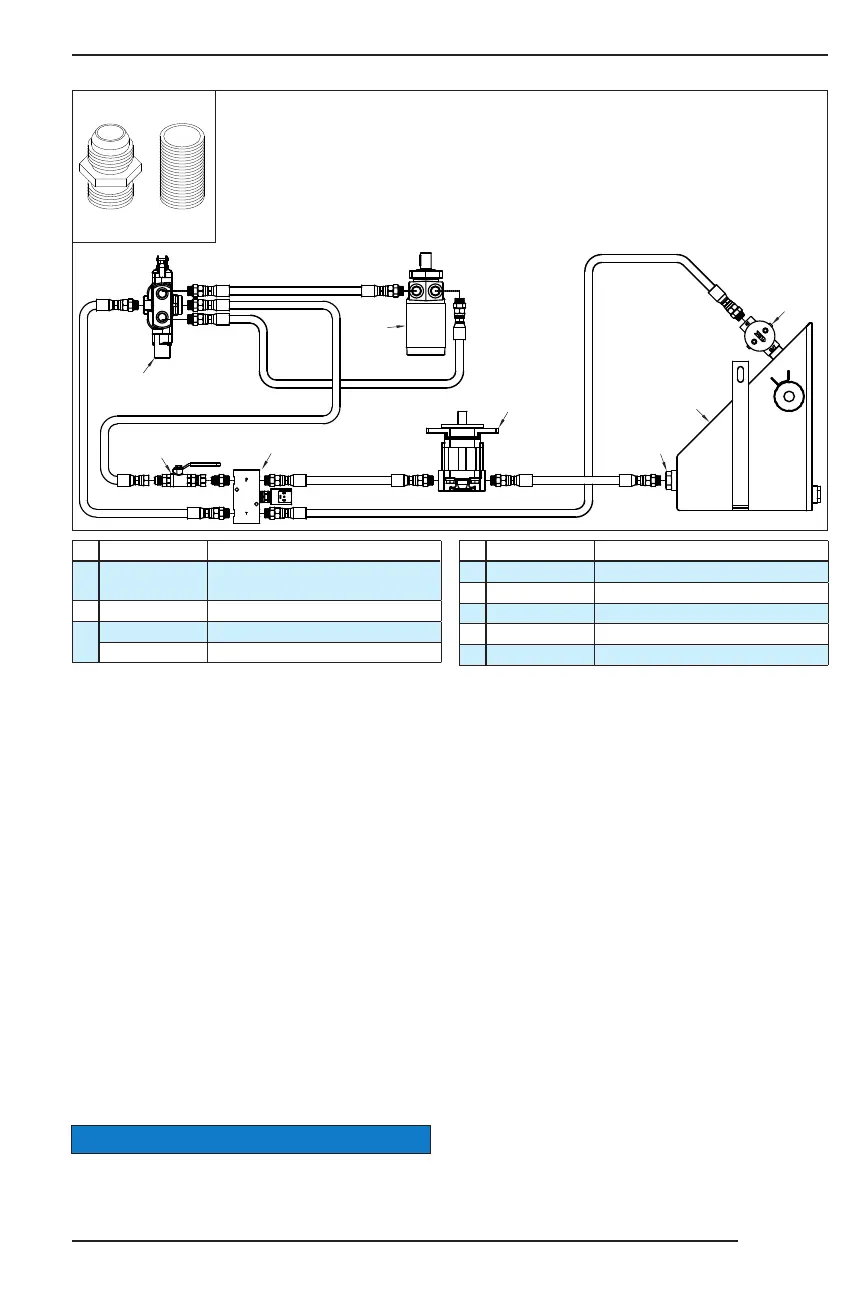
HYDRAULIC SCHEMATIC
# Part Number Description
1
See Pages
80 - 83
Hydraulic Tank
2
900-3900-07 Hydraulic Tank Strainer
3
900-3900-09 Filter Head
900-3900-10 Filter
# Part Number Description
4
** Hydraulic Pump
5
See Page 75 Autofeed Valve
6
See Page 75 In-Line Pressure Check Kit
7
See Page 76 Feedwheel Control Valve
8
900-3973-15 Feedwheel Hydraulic Motor
NOTICE
Examples of
straight ttings.
PIPE
FITTING
JIC / SAE
O-RING
3
2
1
4
5
6
7
8