- 16 -
Wireless charging system 600W specication
For 12V・24V・48V battery
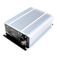
Charging unit (RCS600(B)-CA _)
LED output
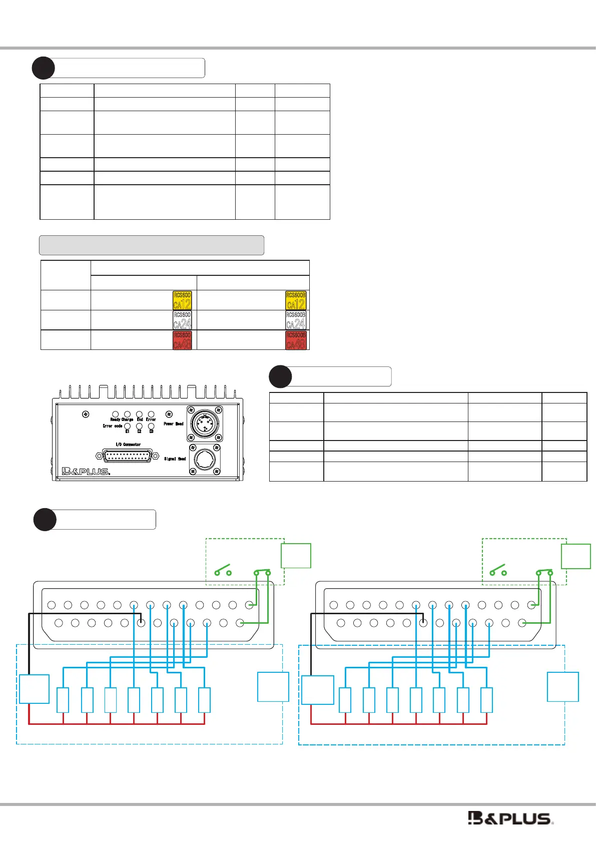
I/O connector
Name Function Display method Output
Ready
Displayed in the stopped charging
state (charging standby state)
Lit Blue Present
Charge Displaying during constant current
or voltage charge operation
Lit Orange Present
End Display the end of charging Lit Green Present
Error Indicates abnormality Lit in Red Present
Error code Display abnormal contents by com
-
bination E1 ~ E3.
Lit in Red Present
For details on how to identify and deal with abnormalities, please refer
to “Identifying and Troubleshooting Abnormalities” on page 28.
normal open type: When you connect Pin 1 and Pin 14, charging will start.Since the charging unit does not operate (charge) unless Pin 1 and Pin 14 are connected, use
the attached Dsub25P start signal ON connector, or turn it ON separately by wiring or on the control side.
normal close type: Since Pin 1 and Pin 14 are connected in advance, charging will start when the power is turned on and the heads are properly facing each other.
Fitting surface of connector (cable wiring side)
Normal open type
Normal close type
13 12 11 10 9 8 7 6 5 4 3 2 1
25 24 23 22 21 20 19 18 17 16 15 14
Dry contact
charging OFF charging ON
18 17 16 8 7 6 5
-
+
20
1
14
* Both NPN and PNP can be wired.The gure is an example of NPN wiring.
For PNP, + and - are reversed.
External
input
signal
Fitting surface of connector (cable wiring side)
Ready
Ready
Charge
Charge
Error
Error
E1
E1
E2
E2
E3
E3
End
End
External
output
signal
DC 24V
power
supply
L
O
A
D
L
O
A
D
L
O
A
D
L
O
A
D
L
O
A
D
L
O
A
D
L
O
A
D
13 12 11 10 9 8 7 6 5 4 3 2 1
25 24 23 22 21 20 19 18 17 16 15 14
18 17 16 8 7 6 5
-
+
20
1
14
External
input
signal
Dry contact
charging ON charging OFF
* Both NPN and PNP can be wired.The gure is an example of NPN wiring.
For PNP, + and - are reversed.
DC 24V
power
supply
External
output
signal
L
O
A
D
L
O
A
D
L
O
A
D
L
O
A
D
L
O
A
D
L
O
A
D
L
O
A
D
Name Function Pin No. Remark
Power ON with power supply 4,20 Output
Ready
ON when charging is stopped
(charging standby state)
5,20 Output
Charge
ON during constant current or con-
stant voltage charge operation
6,20 Output
End ON at the end of charging 7,20 Output
Error ON when abnormal 8,20 Output
E1
E2
E3
The abnormality are indicated by LED
lighting combinations of E1 to E3
16,20
17,20
18,20
Output
I/O connector function
The operation status of the power supply unit is output to
the outside at the same time as the LED display.
As for the operation of the output signal, the output
turns ON when the LED lights up. Each output is an
open collector output circuit with a rated voltage of 24V
and a maximum current of 50mA. Built-in output surge
absorption protection circuit (maximum 39V).
* Do not wire in combinations other than those listed in "I/
O connector functions" above. Wiring to pins other than
those listed above may result in malfunction.
Type code
Normal open Normal close
12V type RCS600-CA12 RCS600B-CA12
24V type RCS600-CA24 RCS600B-CA24
48V type RCS600-CA48 RCS600B-CA48
RCS600B
CA
12
RCS600B
CA
24
RCS600B
CA
48
RCS600
CA
12
RCS600
CA
24
RCS600
CA
48
 Loading...