4. Lamp & Lamp House
Image 4-18
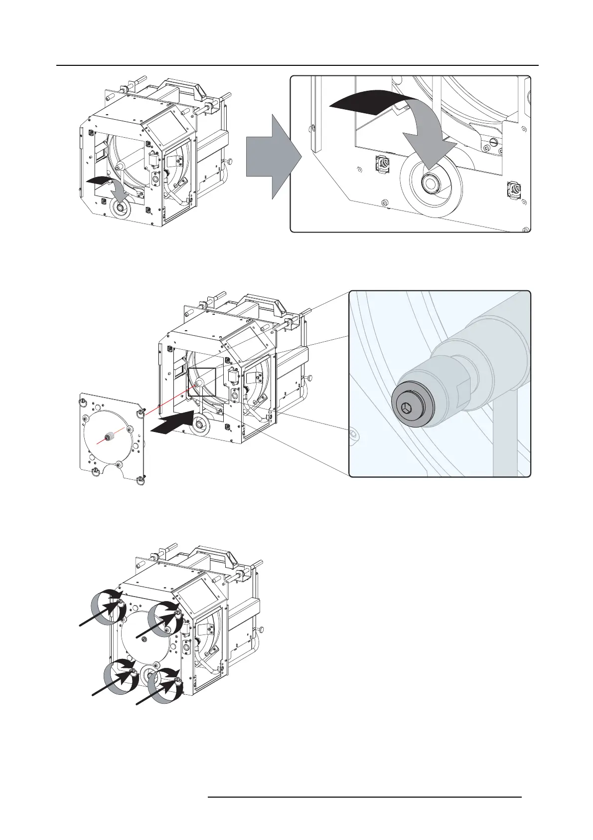
Anode socket installation
7. Reinstall the UV blocker ass embly as illustrated. M ake sure that the xenon lamp is properly supported by the lam p supporting
mechanism in the centre of the UV blocker. U se the opening at the side of the Lamp H ouse to guide the suppo rting pin of the
xenon lamp into the anode supporting mechanism.
Image 4-19
UV blocker installation
8. Secure the UV blocker by fa stening th e four retaining thumbscrews as illustrated.
Note: Please ensure that the thumb sc rews turning wire s are flush w ith the cover o r interference will occu r while inserting t he
lamp hous e into the projector.
Image 4-20
Secure UV blocker
9. Fasten the cathode si
de of the xenon lamp using a hexagon socket head scr ew M6 x 40 and a plain wa sh er as illustrated. Use a
torque of 2,5 N m (1,84 lbf*ft) to fasten the hexagon socket head screw. Use for that a torque wrench w ith a 5 mm Allen socket.
Caution: Make sure that the both pins (reference 10 of image 4 -21) of the cathode adapter rem ain en gaged in the foreseen
slots. Use one hand
to keep the xen on lamp into position while inserting the hexagon socket head screw.
R5905050 DP2K C-SERIES 10/07/2012
31
 Loading...


