Manual 2100-487
Page 13 of 23
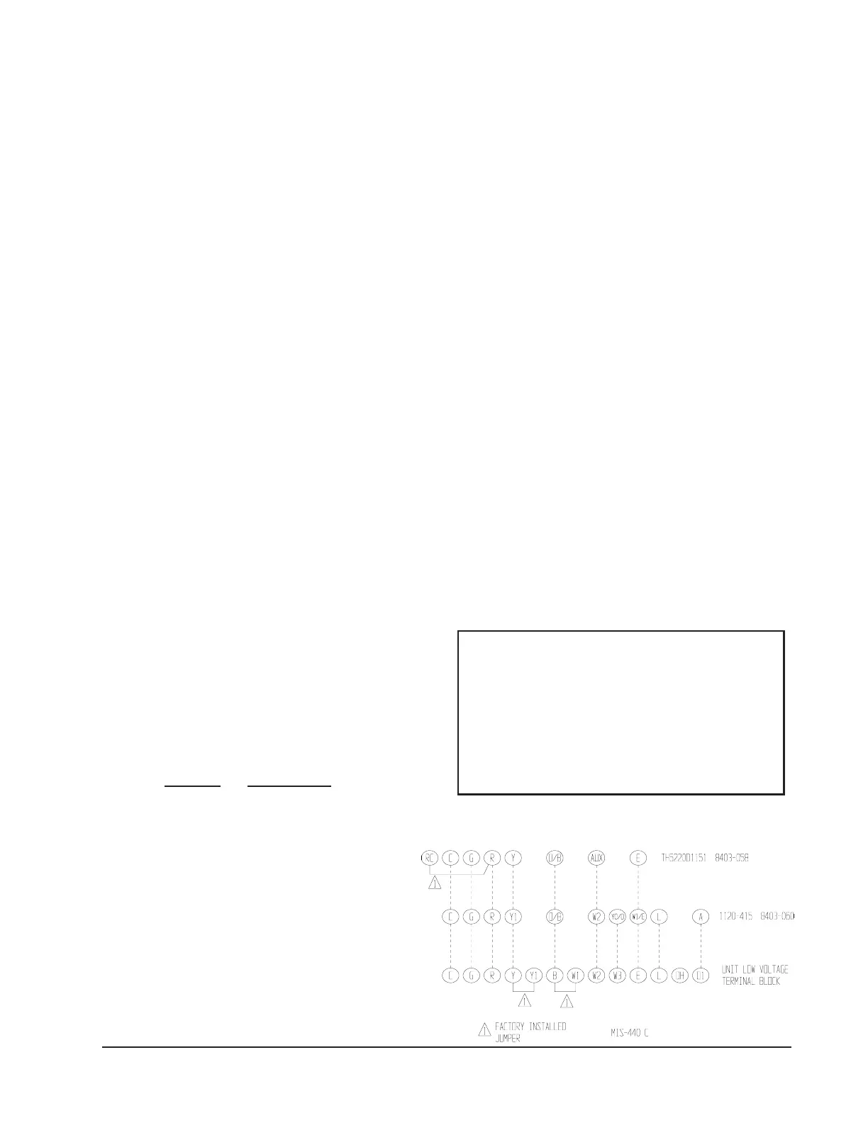
If the #8403-058 thermostat is used, nine (9) wires
should be run from the thermostat subbase to the 24V
terminal board in the unit. If the #8403-060
thermostat/humidistat is used, ten (10) wires should be
run from the thermostat subbase to the 24V terminal
board. A nine (9) or ten (10) wire conductor
(depending on thermostat used), 18 gauge copper
color-coded thermostat cable is recommended. The
connection points are shown in Figure 7.
NOTE: The voltage should be measured at the field power
connection point in the unit and while the unit is
operating at full load (maximum amperage
operating condition).
LOW VOLTAGE CONNECTIONS
These units use a grounded 24 volt AC low voltage circuit.
The “R” terminal is the hot terminal and the “C”
terminal is grounded.
“G” terminal is the fan input.
“Y” terminal is the compressor input.
“B” terminal is the reversing valve input. The reversing
valve must be energized for heating mode.
“R” terminal is 24 VAC hot.
“C” terminal is 24 VAC grounded.
“L” terminal is compressor lockout output. This terminal
is activated on a high or low pressure trip by the electronic
heat pump control. This is a 24 VAC output.
“W2” terminal is second stage heat (if equipped).
“O1”terminal is the ventilation input. This terminal
energizes any factory installed ventilation option.
“E” terminal is the emergency heat input. This terminal
energizes the emergency heat relay.
NOTE: For total and proper control using DDC, a total
of 6 controlled outputs are required (5 if no
ventilation system is installed). For proper
system operation under Emergency Heat
conditions where the compressor needs to be
deactivated, the B-W2-E-G outputs need to be
energized. Removing the Y (compressor)
signal alone turns the compressor off, but does
not activate the additional circuitry embedded in
the heat pump for proper and complete operation.
WIRING — MAIN POWER
Refer to the unit rating plate for wire sizing information and
maximum fuse or “HACR” type circuit breaker size. Each
outdoor unit is marked with a “Minimum Circuit
Ampacity”. This means that the field wiring used must be
sized to carry that amount of current. Depending on the
installed KW of electric heat, there may be two field power
circuits required. If this is the case, the unit serial plate will
so indicate. All models are suitable only for connection with
copper wire. Each unit and/or wiring diagram will be
marked “Use Copper Conductors Only”. These instructions
must be adhered to. Refer to the National Electrical Code
(NEC) for complete current carrying capacity data on the
various insulation grades of wiring material. All wiring
must conform to NEC and all local codes.
WIRING — LOW VOLTAGE WIRING
The electrical data lists fuse and wire sizes (75ºC copper)
for all models, including the most commonly used heater
sizes. Also shown are the number of field power circuits
required for the various models with heaters.
The unit rating plate lists a “Maximum Time Delay Relay
Fuse” or “HACR” type circuit breaker that is to be used
with the equipment. The correct size must be used for
proper circuit protection and also to assure that there will
be no nuisance tripping due to the momentary high
starting current of the compressor motor.
The disconnect access door on this unit may be locked to
prevent unauthorized access to the disconnect. To convert
for the locking capability, bend the tab located in the
bottom left hand corner of the disconnect opening under
the disconnect access panel straight out. This tab will now
line up with the slot in the door. When shut, a padlock may
be placed through the hole in the tab preventing entry.
See Start-up section for information on three phase scroll
compressor start-ups.
230/208V, 1 phase and 3 phase equipment dual primary
voltage transformers. All equipment leaves the factory
wired on 240V tap. For 208V operation, reconnect from
240V to 208V tap. The acceptable operating voltage
range for the 240 and 208V taps are:
LOW VOLTAGE CONNECTIONS
FOR DDC CONTROL
Fan Only Energize G
Cooling Mode Energize Y, G
Heat Pump Heating Energize Y, G, B
2nd Stg Heating Energize G, W2, Y, B
w/Heat Pump (if employed)
Ventilation Energize G, O1
Emergency Heat Energize B, W2, E, G
paTegnaR
042
802
612-352
781-022
FIGURE 7
UNIT 24V TERMINAL BOARD