61-101-00802.EF2 (REV. G) CH. 3
January 7, 2015 Page 35 of 44
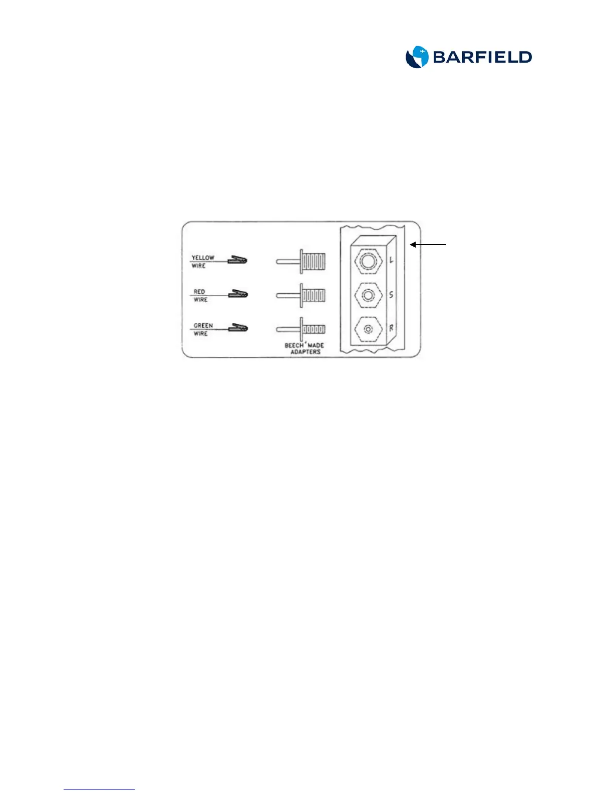
(4) Determine the P/N and physical makeup of the probe-under-test.
(5) Connect the color-coded pin sockets from the probe adapter to the
matching color of the probe lead wire pins or the alligator clips or
probe threaded terminals by thread size and color as applicable.
(6) Connect the socket pin ground lead of the probe adapter to the
ground clip pigtail of the probe adapter. Attach the ground clip to the
grounding area on the probe.
Figure 12 Probes Bench Test
C. Test
(1) Set the test set switch to ON.
(2) Press the PRESS TO READ CAP (pF) pushbutton to display probe
capacitance.
(3) Verify probe capacitance is within the tolerance referenced in Table 4
through Table 7.
(4) If value is not within tolerance, reject probe.
(5) Set the test set ON/OFF switch to OFF.
(6) Rotate the TEST FUNCTION switch to IND AMP.
(7) Set the INSULATION/SYSTEM switch to INSULATION.
(8) Disconnect the pin socket ground lead of the probe adapter from the
ground clip pigtail. Disconnect the small black wire from the ground
clip.
(9) Rotate the INS TEST POINT switch to LO-Z GND.
(10) Set the ON/OFF switch to ON.
(11) Allow time for test set display to stabilize.
(12) Verify the test set display shows less than 50nS. (Refer to Table 1.)
(13) Rotate the INS TEST POINT switch to each remaining position
except SIG/RTN and verify each time that the test set display shows
less than 50nS.
ALL 1900/1900C/1900D
PROBES