61-101-00802.EF2 (REV. G) CH. 3
January 7, 2015 Page 37 of 44
2. INDICATOR BENCH TEST
Note: See PRECAUTIONS and PRELIMINARY sections (Chapter 1).
Note: Failure to calibrate the system after performing the indicator bench test will
result in an inaccurate fuel quantity reading.
A. Test Set Preparation
(1) Set the ON/OFF switch to OFF.
(2) Rotate the TEST FUNCTION switch to CAP SIM CAL (NORM SYS).
(3) Set the INSULATION/SYSTEM switch to SYSTEM.
(4) Set the MAIN/TOT-AUX/NAC switch to MAIN/TOT.
(5) Set the 200 (pF)/1000 (pF) switch to 200 (pF).
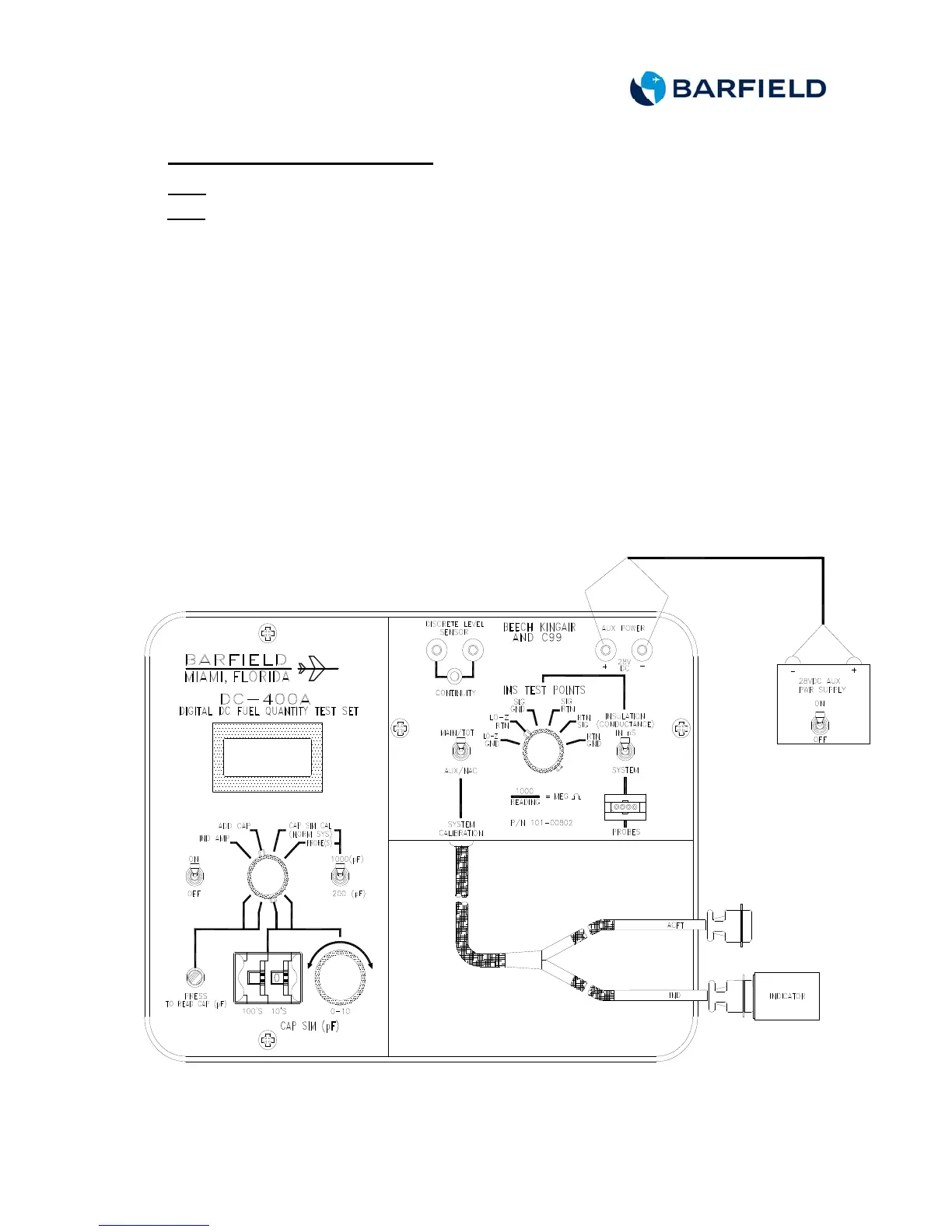
B. Connecting Test Set
(1) Determine the number of pins on the connector and connect the test
set as shown in Figure 13 or Figure 14.
(2) Connect the 28 VDC power supply to the test set AUX POWER jacks.
Observe polarity.
Figure 13 Indicator Bench Test Connection