61-101-00802.EF2 (REV. G) CH. 3
January 7, 2015 Page 38 of 44
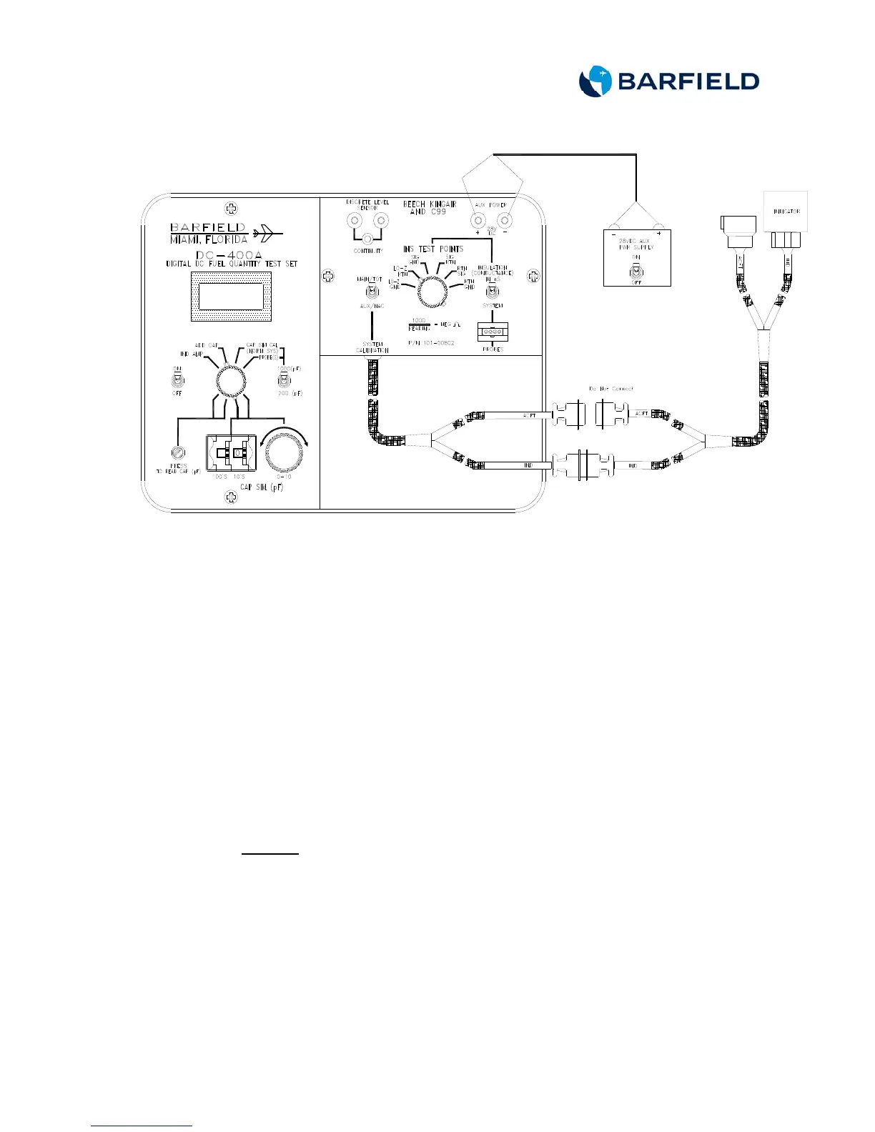
Figure 14 Indicator Bench Test Connection
C. Test Procedure
(1) Set the test set ON/OFF switch to ON.
(2) Set the CAP SIM (pF) 100’s to 1. Set the 10’s thumbwheels to 5 for
all 1900 models.
(3) Press and hold the PRESS TO READ CAP (pF) pushbutton while
adjusting CAP SIM (pF) control knob to obtain a test set reading of
156.5 pF (for UA and UB serial numbers) or 159.4 (for UC and UE
serial numbers).
(4) Release the pushbutton.
(5) Rotate the TEST FUNCTION switch to IND AMP.
(6) Set the 28 VDC power supply ON/OFF switch to ON.
Caution: Do not tap bezel of instrument to vibrate. To remove friction,
gently tap adjacent panel or rear housing of indicator before
taking readings.
(7) Verify the indicator reads zero lbs.
(8) If reading is not zero, adjust EMP 1/E 1 or E located at rear of
indicator.
(9) If the indicator will not give a zero reading, replace the indicator.
(10) Rotate the TEST FUNCTION switch to CAP SIM CAL (NORM SYS).