56-101-01501_01502 Revision D Page | 17
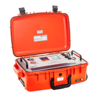
B. Connecting Test Set
(1) Position the equipment conveniently for the following procedures.
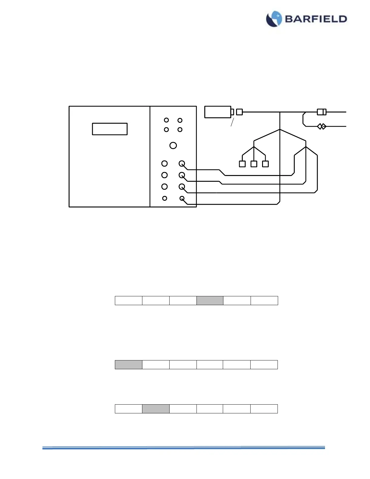
(2) Connect to the Test Set the Adapter Cable specific for the Aircraft being tested, as
shown in Figure 16 or as directed in the Adapter Cable Instructions.
(3) Connect the Adapter Cable between the Indicator and the aircraft wiring plug.
(4) Connect the ground lead from the adapter (if so equipped) or from the Test Set GND
receptacle, to a secure airframe ground.
Figure 16 Aircraft Capacitance Test Configuration
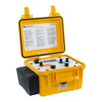
C. Test Procedure
Refer to the specific Maintenance Manuals for proper procedures and calibration values.
(1) Press PWR to turn test set ON.
(2) Allow initialization to complete.
(3) Press ENT to accept last used Frequency or key in new frequency, then press ENT.
(4) Press F4 to select CAPacitance Measure.
(5) Press RANGE to select AUTO ranging or 400 pF, 4,000 pF or 40,000 pF range.
(6) Press F1 to measure TANK capacitance, if not already highlighted.
Note: Press F5 to Zero adapter cable stray capacitance. Subsequent measurements
are offset by the stored value.
(7) Observe the display reading and verify if the value is within specified tolerance.
(8) Press F2 to test the Compensator.