(14) This completes the AIRCRAFT CAPACITANCE TEST.
(15) Press PWR to turn test set OFF.
(16) Disconnect the Adapter Cable from the Test Set.
(17) Disconnect the Adapter Cable from the Aircraft and from the Indicator.
(18) Return the aircraft to its original configuration.
9. INDICATOR TEST
The Fuel Quantity Indicator may contain all the system measurement circuitry, or a major
portion may be contained in a separate unit referred to as a signal conditioner or amplifier. The
procedure is similar, only the location of the units and their adjustments will be affected.
CAUTION: THE PROCEDURE INDICATED IN THIS SECTION IS NOT FOR A
CALIBRATION. ANY ADJUSTMENT PERFORMED HERE MUST THEN BE
FOLLOWED BY AN ACTUAL CALIBRATION.
A. Aircraft Preparation
(1) The Aircraft does not need to be defueled for this test. The level of fuel is irrelevant.
CAUTION: FUEL QUANTITY, REFUEL, AND DEFUEL POWER MUST BE
TURNED OFF WHILE ACCESSING AND BEFORE ANY HARNESS,
CABLE OR CONNECTOR IS REMOVED. POWER MUST REMAIN
OFF UNTIL CONNECTIONS ARE MADE AS SPECIFIED AND UNTIL
POWER REQUIREMENT IS CALLED OUT.
(2) Open appropriate Fuel Quantity System circuit breaker(s).
CAUTION: REFER TO AIRCRAFT MAINTENANCE MANUAL FOR ACCESSING
PROCEDURES, FOLLOW ALL PRECAUTIONS THEREIN.
(3) Gain access to the cockpit indicator or the appropriate Fuel Quantity System electrical
connector(s) necessary for this procedure.
(4) Disconnect at the cockpit indicator or the appropriate electrical connector(s).
B. Connecting Test Set
(1) Position the equipment conveniently for the following procedures.
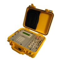
(2) Connect to the Test Set the Adapter Cable specific for the Aircraft being tested, as
shown in Figure 17 or as directed in the Adapter Cable Instructions.
(3) Connect the Adapter Cable between the Indicator and the aircraft wiring plug.
(4) Connect the ground lead from the adapter (if so equipped) or from the Test Set GND
receptacle, to a good airframe ground.