56-101-01501_01502 Revision D Page | 19
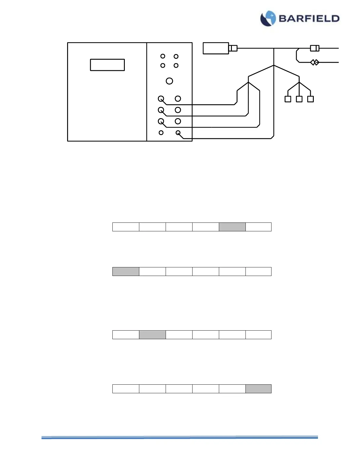
Figure 17 Aircraft Indicator Test Configuration
C. Test Procedure
Refer to the specific Maintenance Manuals for proper procedures and calibration values.
(1) Press PWR to turn test set ON.
(2) Allow initialization to complete.
(3) Press ENT to accept last used Frequency or key in new frequency, then press ENT.
(4) Press F5 to select the SIMulator function.
(5) Press MODE for IN (default) if the COMPensator simulator is needed.
(6) Press F1 to select TANK simulator (default), if not highlighted.
(7) Press RANGE to select 4,000 pF or 10,000 pF as desired.
(8) Using the keypad, enter the Empty TANK capacitance.
a. Example for 123.4 pF: press “1”, then “2”, then “3”, then “.”, then “4” then ENT
(9) Press F2 to select COMPensator.
(10) Using the keypad, enter the Empty COMP capacitance.
(11) Press BACK to return to Main screen.
(12) Press F6 to select CAL.
CHASSIS
AIRFRAMEGND
A/CIND
ACFT
IND
DFQ40K
SM GND
COMP
HI-Z
Com Link
-
+
INPUT
4W
LO-Z
HI-Z
COMP
GND
LO-Z
HI-Z COMPLO-Z
INDICATOR
WIRING
AIRCRAFT
A/CIND
Adapter Cable