56-101-01501_01502 Revision D Page | 21
(1) Defuel the Aircraft.
CAUTION: FUEL QUANTITY, REFUEL, AND DEFUEL POWER MUST BE
TURNED OFF WHILE ACCESSING AND BEFORE ANY HARNESSES,
CABLES, OR CONNECTORS ARE REMOVED. POWER MUST
REMAIN OFF UNTIL CONNECTIONS ARE MADE, AS SPECIFIED
AND UNTIL POWER REQUIREMENT IS CALLED OUT.
(2) Open appropriate Fuel Quantity System circuit breaker(s).
CAUTION: REFER TO AIRCRAFT MAINTENANCE MANUAL FOR ACCESSING
PROCEDURES, FOLLOW ALL PRECAUTIONS THEREIN.
(3) Gain access to the cockpit indicator or the appropriate Fuel Quantity System electrical
connector(s) necessary for this procedure.
(4) Disconnect at the cockpit indicator or the appropriate electrical connector(s).
(5) It may be necessary to position an aircraft tank select switch and/or an Adapter Cable
select switch for this procedure.
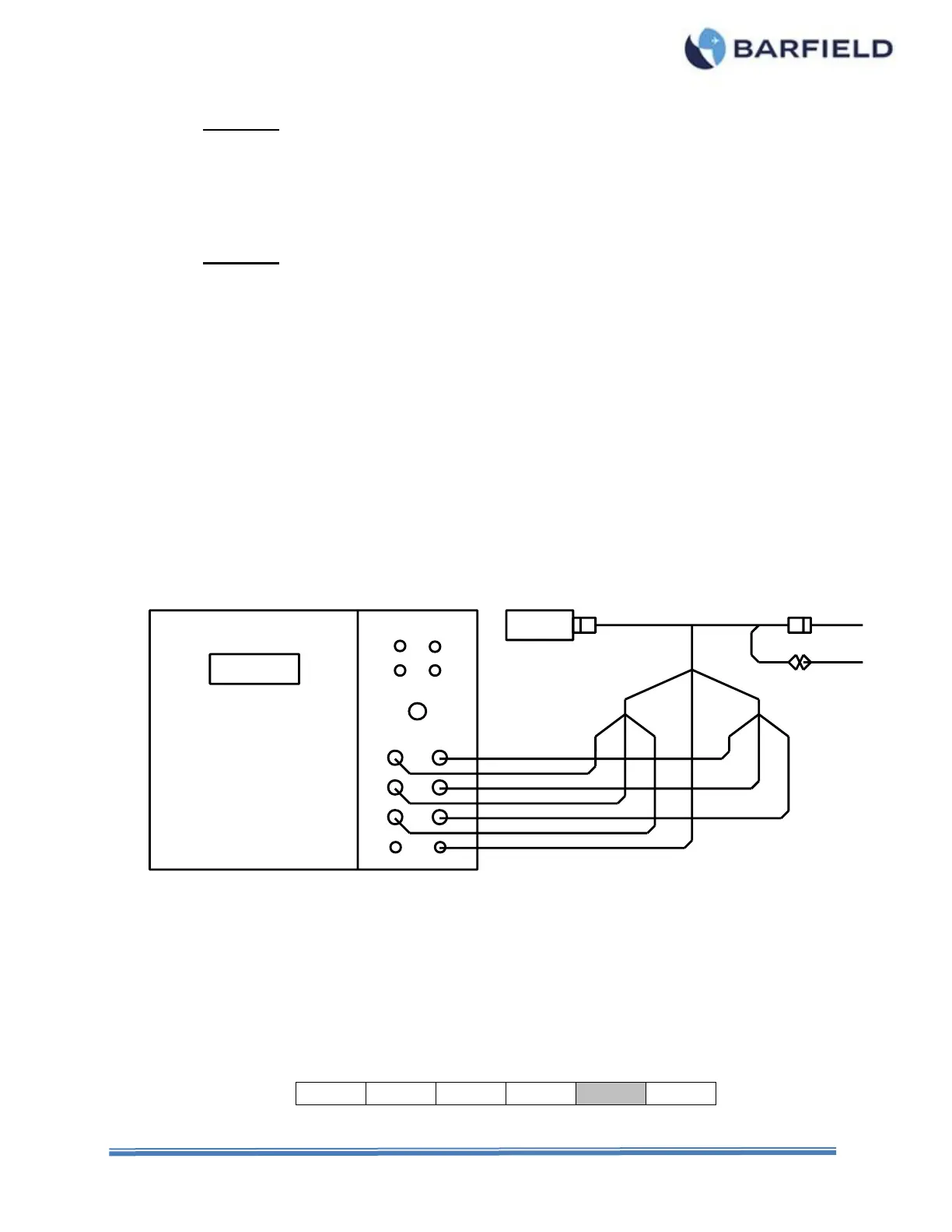
B. Connecting Test Set
(1) Position the equipment conveniently for the following procedures.
(2) Connect to the Test Set the Adapter Cable specific for the Aircraft being tested, as
shown in Figure 18 or as directed in the Adapter Cable Instructions.
(3) Connect the Adapter Cable between the Indicator and the aircraft wiring plug.
(4) Connect the ground lead from the adapter (if so equipped) or from the Test Set GND
receptacle, to a secure airframe ground.
Figure 18 Aircraft Preferred Calibration Configuration
C. Test Procedure
Refer to the specific Maintenance Manuals for proper procedures and calibration values.
(1) Press PWR to turn test set ON.
(2) Allow initialization to complete.
(3) Press ENT to accept last used Frequency or key in new frequency, then press ENT.
(4) Press F5 to select the SIMulator function.