14
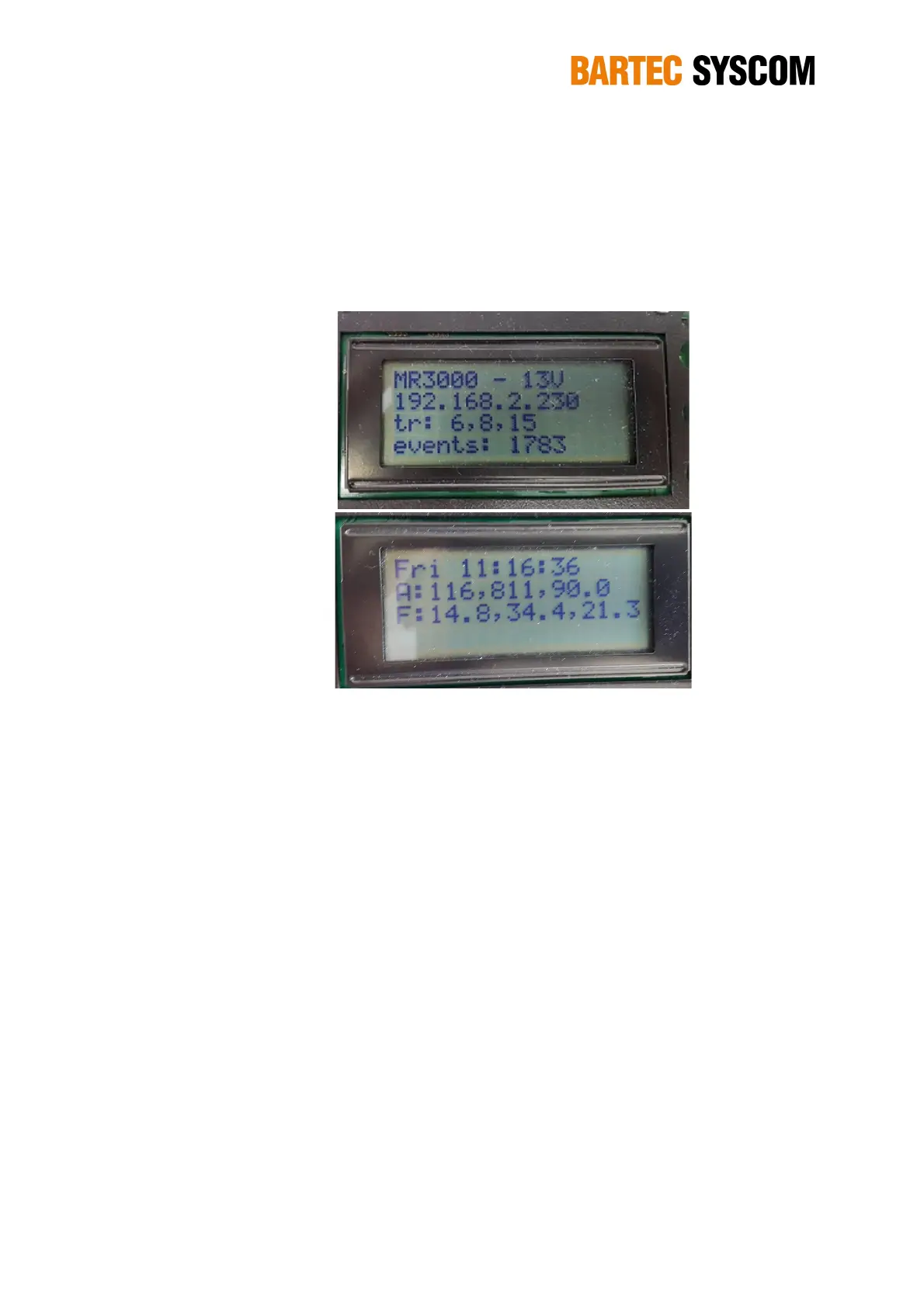
LINE 2. IP address of the instrument.
LINE 3. Values set for the trigger on the three axes. When trigger is 'disabled' or its mode
is 'STA/LTA', this is clearly shown on the LCD display
LINE 4. Number of events recorded on the SD card.
a)
b)
Figure 2.4.3. First (a) and second (b) screen of the internal display of the MR3000SB.
The second screen (Figure 2.4.3b) shows the information related to the last event:
LINE 1. Day and time of the event
LINE 2. Vibration values on the three axes. “A” means amplitude (in mg)
LINE 3. Dominant frequency calculated on the three axes. “F” means frequency (Hz)
The first screen last 10 seconds while the second screen lasts 15 seconds.
2.4.2. MEMS acceleration sensor
The MR3000SB is equipped with an internal acceleration MEMS sensor MS2008+. It is placed in
the zone under the display.
The main characteristics of the sensor are:
Measuring range: ±4 g
Dynamic range: typ. 100 dB (@100 Hz BW)
Frequency range: Frequency response DC to 600Hz
Sensitivity: 1.25 V/g (differential)
Noise: typ. 7ug/sqrt(Hz)
It does not require to be periodically re-calibrated since MEMS sensors are very stable during all
their lifetime.