SURFACE PREPARATION SYSTEM OWNER’S MANUAL & PARTS BOOK
BARTELL MORRISON INC. BARTELL MORRISON (USA) LLC
375 ANNAGEM BLVD, MISSISSAUGA, ONTARIO, CANADA, L5T 3A7, 905-364-4200 FAX 905-364-4201
25 INDUSTRIAL DRIVE, KEYPORT, NEW JERSEY, USA, 07735, 732-566-5400 FAX 732-566-5444
- 13 -
BEARING REPLACEMENT PROCEDURES
IMPORTANT: Disengage power supply. Do not attempt
replacement while machine is operable.
A)
3BSEALED BEARING REPLACEMENT – OUTBOARD
SIDE
4BRemove drive shaft and cutter cage assembly as per
cutter change procedure below. Loosen and remove
bearing block flange by removing screws and
lockwashers. Using a soft drift, drive out and remove
old bearing. Clean parts which will be re-used.
Carefully press new bearing into flange. Take extreme
care to maintain aligned installation. Do not press
sleeve into position if misaligned. Mount bearing block
to side of housing and tighten bolts when bearing
block is in a free spin position.
B) 5BBEARING REPLACEMENT – DRIVER OR “V” BELT
SIDE
Remove belt guard and “V” belt. Loosen two set
screws, remove pulley and remove key. Remove
bearing block assembly by removing screws and lock
washers. Remove snap ring and slip ring. Using a soft
drift, drive out spindle. Take care not to burr or flare
spindle. Remove cover plate being certain the plate
fits flush. Carefully press new bearing into block,
clean and install bearing cover plate. Press drive
spindle into block. Install slip ring and snap ring.
Center and install spindle assembly to housing. Re-
install pulley and key. Ensure pulley butts flush
against shoulder or spindle. NOTE: When removing
spindle or sleeve, care must be taken not to damage
or distort these parts. A soft drift is recommended to
prevent damage.
CUTTER CAGE REMOVAL & CUTTER CHANGE
To remove the cutter cage from the machine.
1. Make sure that the power source is disconnected.
With gas models turn off fuel supply to engine and
disconnect sparkplug; unplug electric unit; disconnect
air supply on air unit.
2. Tilt machine back onto the handle. (If your unit is
equipped with a Honda GX engine, unit must be tilted
forward to change cutters or cylinders will be flooded
with oil).
CUTTER CAGE REMOVAL & CUTTER CHANGE
(Cont.)
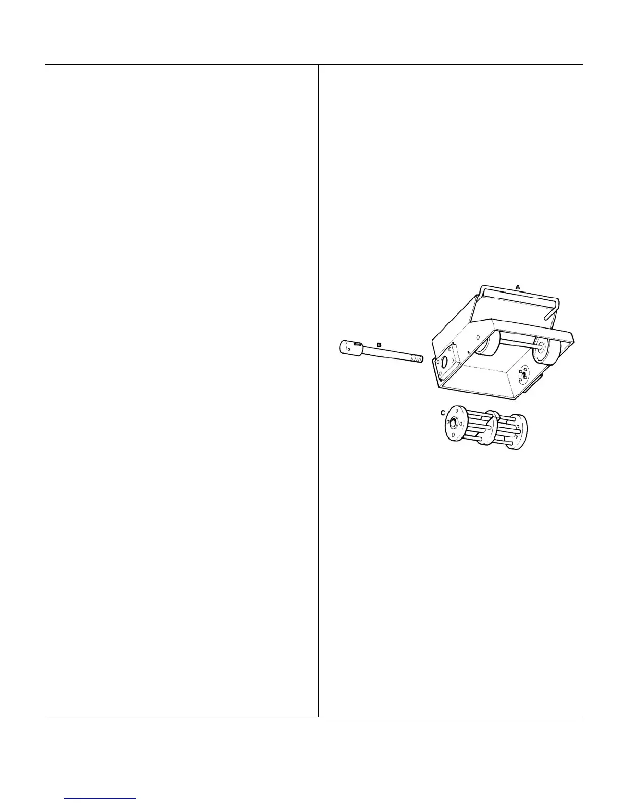
3. Facing the underside of the machine housing (figure
3-A) place a bar between the cutter rods to jam
cage C.
4. Remove end cap and with a 1” (26 mm) socket
loosen and remove the shaft by turning in clockwise
direction.
OR
Remove end cap and shaft guard to insert a drift pin
into the hole on the main shaft B and turn shaft
clockwise to loosen and remove shaft.
5. Disengage the cage from the drive pins by moving
to the left. (The cage on the Honda GX machines
will move to the right). Remove cage.
Figure 3-A
EDGER CAGE REMOVAL
1. Make sure that the power source is disconnected.
With gas models turn off fuel supply to engine and
disconnect sparkplug; unplug electric unit;
disconnect air supply on air unit.
2. Tilt machine back onto handle. (If your unit is
equipped with a Honda GX engine, unit must be
tilted forward to change cutters or cylinders will be
flooded with oil).
3. Using a 15/16” socket or wrench, turn head of shaft
(G) clockwise to loosen.
4. While turning the shaft outwards, cage will move
towards the outer edge as well. Free cage from
locking pins on shaft by pushing cage back towards
main housing (A). turn shaft out and move.
5. Cage will be free to remove from edger.