M.DRIVE.DB-21.GEN.ENG
Ed.
2021 Rev.04
Pag. 30 di 31
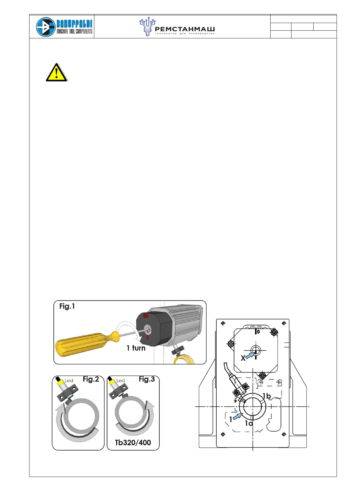
13.5 ZERO SENSOR SETTING
In order to execute this procedure, it is necessary to supply the proximity switch
(24Vdc) and have pressure in the lock/unlock turret circuit.
- Supply the drive with only 24Vdc (X2 Input Connector)
- Turret must be locked in position n° 1
- Remove the motor cover
- Loosen the two socket head screw (1a 1b) that fix the ring (1)
- Unlock the turret acting on valve
- With a screwdriver twist the motor shaft for 1 turn in clockwise direction as shown in Fig.1
- Rotate the ring (1) in clockwise direction (Fig.2) (counter clockwise for Tb320/400 Fig.3) till proximity is
activated.
- Lock the two socket head screws (1a 1b)
- Twist the motor shaft back one turn
- Lock the turret acting on valve
- Reassemble the motor cover
-Switch OFF the machine, reconnect plug M1 (if removed)
-When machine will be ON it is possible to command a tool change
Note
Phasing the cam does not change the position of the resolver so it's not necessary repeat the acquisition of
resolver position.
After removing the cover, ensure that the X mark (on the motor rotator) on the motor shaft is pointing down
(6o’clock), opposite to sign 0 on the motor cover.
If the X sign is not in position, disassemble the motor, rotate the shaft orienting the sign X down and
reassemble it.
Then proceed with the sequence above and before to make a tool change repeat the acquisition of the resolver
position (chapter 16.2)