EasyManua.ls Logo

Baruffaldi DB21 - User Manual

Baruffaldi DB21
34 pages
Print Icon
To Next Page IconTo Next Page
Loading...
INSTALLATION AND USE MANUAL
SERVO DRIVE TYPE DB21
M.DRIVE.DB-21.GEN.ENG
Ed.
2022
Rev.11
Pag.
1 di 34
INSTALLATION AND USE MANUAL
Servo Drive type DB-21
Suitable for turrets models:
Linea Archimede: TB/TBMA/TBMR
Linea Michelangelo: TAB
Linea Leonardo: TC/TCMA/TCMR
Linea Galileo: TBHMA-C/TBHMR-C
Linea Ecoline: TBH/TBHMA

Questions and Answers

  • R
    Robert Hamilton MDSep 9, 2025
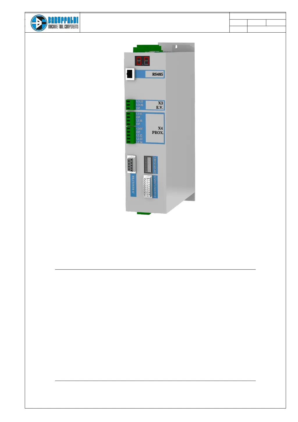
    What to do if Baruffaldi Servo Drives show Unlock proximity switch in short circuit [Li.12, Li.13=On]?
    • P
      Pamela FrancoSep 9, 2025
      If the unlock proximity switch remains On (Li.12) during the locking sequence on Baruffaldi Servo Drives, creating a short circuit [Li.12, Li.13=On], check the functionality of unlock proximity switch.
  • J
    Jessica EricksonAug 23, 2025
    Why is my Baruffaldi DB21 turret not locked at the start up [Li.13=Off]?
    • M
      Michael BrownAug 23, 2025
      If the Baruffaldi Servo Drives turret isn't locked at startup (indicated by Li.13=Off), the alarm is activated because the drive commands the turret to lock, but the lock proximity switch isn't engaged. To resolve this, check the functionality of the proximity switch, inspect the hydraulic/pneumatic circuit, and verify the electrovalve/auxiliary relais connection.
  • J
    Jackson PenaAug 25, 2025
    What to do if Baruffaldi Servo Drives show a Resolver Malfunctioning error?
    • E
      Elizabeth ThompsonAug 25, 2025
      If your Baruffaldi Servo Drives system reports a Resolver Malfunctioning error, it means the signal from the resolver is either low or absent. You should: * Check the wiring of connector J2 and the connections in the terminal block signals on the turret. * Inspect the cable for integrity and continuity. * Ensure that the drive is correctly set for the motor in use.
  • D
    Dennis SandersAug 27, 2025
    What to do if Baruffaldi DB21 show a Positioning Error?
    • G
      gjoyceAug 27, 2025
      If a positioning error occurs with Baruffaldi Servo Drives, it means the turret is locked in a position different from what was expected at the end of a position inquiry. The resolver value calculated differs from the final position resolver. Begin by verifying that the drive SETUP matches the turret in use (K2/K5/K3) at startup. Also, ensure the dipswitch is properly set according to the turret in use, considering the transmission ratio and the number of stations.
  • D
    Dawn ContrerasAug 28, 2025
    What to do if Baruffaldi DB21 Servo Drives show a Motor PTC error?
    • R
      ryanchandlerAug 28, 2025
      If Baruffaldi Servo Drives display a Motor PTC alarm, it indicates that continuity between pin 1 and 2 of J2 is not detected, suggesting the motor's temperature sensor (PTC) has detected excessive winding temperature. Ensure the ambient temperature near the motor is within allowed limits. If the alarm persists when the motor is cold, check the wires connecting the sensor (pins 1 and 2 of J2 on the board and the terminal turret).
  • R
    reginamathewsAug 29, 2025
    Why is there no signal from lock proximity switch [Li.12=Off, Li.13=Off] on Baruffaldi Servo Drives?
    • K
      Kari FowlerAug 29, 2025
      If there's no signal from the lock proximity switch (Li.13) and the unlock proximity switch is also off (Li.12) after 30 seconds from the locking command (Lo.16) on Baruffaldi Servo Drives, check the functionality of the proximity switch. Remove the upper cover to verify that the movement of the pin is not hindered. Also, inspect the hydraulic/pneumatic circuit if present, check the turret setup made with the dipswitch, and check the drive configuration K2/K5.
  • V
    Victor ThorntonSep 18, 2025
    What to do if The lock Px switch signal has been lost during work (turret indexed) [Li.13=Off] on Baruffaldi DB21 Servo Drives?
    • J
      Jonathan VargasSep 18, 2025
      If the lock proximity switch signal (Li.13) is lost during the working phase (turret indexed) on Baruffaldi Servo Drives, check the functionality of the lock proximity switch.
  • P
    phillipsemilySep 22, 2025
    What to do if The unlock proximity switch signal has been lost during rotation [Li.12=Off] on Baruffaldi DB21 Servo Drives?
    • J
      Jennifer BuchananSep 22, 2025
      If the unlock proximity switch signal (Li.12) is lost during rotation on Baruffaldi Servo Drives, check the functionality of the unlock proximity switch. Also, check the connection on turret pin 12 (both client and turret side) and on the M4 connector.
  • Y
    youngsusanSep 8, 2025
    What to do if Baruffaldi DB21 Servo Drives report a parity error?
    • G
      Gail JamesSep 8, 2025
      If Baruffaldi Servo Drives report a parity error, it means that before the turret is unlocked, when the START command is sent, the parity bit is not set correctly. To fix it, check the connection J1 pin 23 with the PLC, ensure that the PLC program correctly handles the parity bit, and verify that there is a delay in the PLC of at least 50ms between setting the position and parity to the START command.
  • S
    Sarah BrandtSep 4, 2025
    What causes Zero Search Error in Baruffaldi Servo Drives?
    • M
      Molly RobertsSep 4, 2025
      A Zero Search Error on Baruffaldi Servo Drives happens when, at the end of a zero search (even a hidden one), the turret is closed, and the resolver value differs from the value stored during the resolver acquisition sequence. If the turret has reached station N°1, repeat the acquisition of the position resolver. Otherwise, with the turret locked in station N°1, remove the back cover of the turret and verify the mechanical position of the zero using the instructions in the turret manual.

Summary

GENERAL WARNINGS

INSTALLATION WARNING

Warning regarding the input voltage setting for the drive installation.

SAFETY AND INSTALLATION

SAFETY CONSIDERATIONS AND INSTALLATION CONSTRAINTS

Important safety considerations and constraints for installing the servo drive.

EMC ADVICES

Recommendations for ensuring electromagnetic compatibility for the drive.

SPECIFICATIONS

PARAMETERS AND LIMITS OF USE

Key technical parameters and operational limits for the servo drive.

VOLUME AND WEIGHT

Physical dimensions and weight specifications of the servo drive unit.

ELECTRICAL CONNECTIONS

X1 POWER SUPPLY

Details for connecting the main power supply to terminal X1.

X2 LOGIC SUPPLY

Details for connecting the logic power supply to terminal X2.

X3 ELECTROVALVES OUTPUT

Output connections for electrovalves on terminal X3.

X4 EXTRA PORTS

Output connections for extra ports, including proximity sensors on X4.

J2 ANGULAR POSITION TRANSDUCER

Input details for the angular position transducer (resolver) on J2.

J1 DIGITAL INPUT;OUTPUT

Digital input/output connections for interfacing via J1.

X5 MOTOR CONNECTIONS

Output connections for the motor phases (U, V, W, T) on X5.

DRIVE AND TURRET LAYOUT

TURRET CONNECTIONS

4.1 LINEA ARCHIMEDE & ECO-LINE

Wiring for Linea Archimede and Ecoline turrets with standard boards.

4.2 LINEA ARCHIMEDE (TBMR;TBYR HARTING)

Wiring for TBMR/TBYR turrets using Harting connector.

4.3 LINEA MICHELANGELO (TAB)

Wiring for Linea Michelangelo TAB turrets.

4.4 LINEA LEONARDO (TC;TCMA;TCMR;TCMQ)

Wiring for Linea Leonardo turrets with plug-in connectors.

J1 INPUT;OUTPUT

5.1 CONSENT TO WORK

Conditions required for the drive to start operation.

5.2 POSITION FEEDBACK

Explanation of how position feedback signals are communicated.

5.3 ALARMS

Information on how alarms are communicated via output signals.

5.4 START COMMAND

Timing requirements for the start command signal.

5.5 OPERATIVE MODE

Details on the different operative modes selectable for the drive.

5.6 POSITION REQUIRED

Information on setting the required position inputs.

DIPSWITCH SETTING (FOR TURRET TYPE SELECTION)

TURRET SELECTION

Setting the turret type, number of positions, and dynamic profile.

CUSTOM PROFILE

How to set a custom profile manually via software.

WORKING LOGIC AND POSITIONING INQUIRY

ZERO SEARCH PROCEDURE

Procedure for performing zero search after drive startup or reset.

HIDDEN ZERO SEARCH

Procedure for hidden zero search when position is not indexed.

OPERATIVE MODE

MODE 0 - RESET; EMERGENCY

Mode for reset, emergency, and clearing alarms.

MODE 1 - AUTOMATIC POSITIONING

Default mode for shortest path positioning and zero search.

MODE 4 - JOG MODE; MANUAL OPERATION

Jog mode for manual tool changes or pre-setting.

MODE 7 - RESOLVER ACQUISITION

Alternative procedure for resolver acquisition.

DRIVE SET-UP (NEW TURRET INSTALLATION)

VOLTAGE SETTING PROCEDURE

Procedure for setting the input voltage for the drive.

TURRET TYPE AND PARAMETER SETTING

Setting turret type, number of positions, and dynamic profile via dipswitches.

DUTY CYCLE (BARUFFALDI;DIN5482 LIVE TOOL TOOLING SYSTEM)

DUTY CYCLE (BMT;DIN5480;DIN1809 LIVE TOOL TOOLING SYSTEM)

DRIVE ALARM

VOLTAGE ALARMS

Alarms related to voltage issues and dipswitch changes.

HARDWARE ALARMS

Alarms related to EEPROM, sensors, and calibration.

TURRET UNLOCKING ALARMS

Alarms related to turret unlocking failures.

TURRET POSITIONING ALARMS

Alarms related to turret positioning and rotation timeouts.

RESOLVER ALARMS

Alarms related to resolver malfunctioning or motor PTC.

POSITIONING ALARMS

Alarms related to parity errors or non-existing positions.

TROUBLESHOOTING

POWER SUPPLY AND VOLTAGE ISSUES

Troubleshooting undervoltage, power errors, and high current peaks.

HARDWARE AND CALIBRATION ERRORS

Troubleshooting EEPROM, sensor, and thermal calibration errors.

TURRET LOCKING;UNLOCKING FAULTS

Troubleshooting turret locking and unlocking signal issues.

TURRET POSITIONING AND ROTATION ERRORS

Troubleshooting turret state during positioning and rotation timeouts.

RESOLVER AND MOTOR ISSUES

Troubleshooting resolver malfunctions and motor PTC issues.

LOGIC AND COMMUNICATION ERRORS

Troubleshooting parity, position, and mode communication errors.

COMPATIBILITY WITH PREVUIOUS VERSIONS

DRIVE AND MOTOR TIMELINE

Timeline showing drive and motor model evolution.

TURRET SERIAL NUMBER IDENTIFICATION

How to identify turret type and model from serial number.

DRIVE REPLACEMENT (SET-UP AND SETTING)

SEQUENCE OF OPERATIONS N°2 (VOLTAGE SETTING)

Procedure for setting the input voltage during drive replacement.

SEQUENCE OF OPERATIONS N°3 (TURRET CHARACTERISTICS)

Procedure for setting turret type and parameters during replacement.

MOTOR REPLACEMENT (ARCHIMEDE;ECOLINE)

DISASSEMBLING THE MOTOR

Steps for safely removing the motor from the turret.

PUTTING ON NEW MOTOR

Steps for installing a new motor onto the turret.

MOTOR REPLACEMENT (LEONARDO)

DISASSEMBLING THE MOTOR

Steps for removing the motor for Linea Leonardo turrets.

PUTTING ON NEW MOTOR

Steps for installing a new motor for Linea Leonardo turrets.

RESOLVER ACQUISITION

CABLE ADAPTER FOR OLD DRIVE INTERFACING

PINOUT BARUFFALDI ADAPTER

Pinout details for the Baruffaldi adapter cable.

INTERFACE CONNECTIONS AND SIGNALS

Details on logic supply, position feedback, and alarm bits.

Baruffaldi DB21 Specifications

General IconGeneral
BrandBaruffaldi
ModelDB21
CategoryServo Drives
LanguageEnglish

Related product manuals