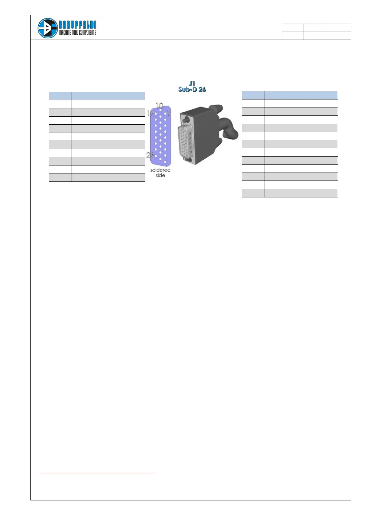
5. J1 INPUT/OUTPUT
5.1 CONSENT TO WORK
It is possible to start to work only when both signals are active:
- ST INDEX (J1pin.8) = turret in position
- ST LOCK (J1pin.17) = turret closed
In addition to these two signals is possible using the binary outputs of the POSITION FEEDBACK to make sure
that the turret is in the position required.
Outputs are reset:
- in case of alarm
- during rotation of the turret
- drive reset (mode = 0)
5.2 POSITION FEEDBACK
n° 5 binary outputs communicate the position of the turret. The position can be seen on display in the front of
the drive.
The outputs are only active with turret indexed ie has already been done a positioning or zero search (even
hidden).
The outputs are active when:
- the turret is closed in the position
- no alarms are present
- the drive is not in reset mode (mode bit off)
The position feedback is in binary code (see table at left) without the parity bit
5.3 ALARMS
N°5 binary outputs communicate the presence of an active alarm. In order to facilitate the
diagnosis, the active alarm is displayed on the front display.
The activation determines:
- rotation stop
- deactivation of outputs St index, St lock and position feedback.
To perform a new positioning is necessary to reset the alarm by setting the operating mode zero.
5.4 START COMMAND
Should be: min 100ms /Max 200ms
It 'important that the command is given with a delay of at least 50ms after the setting of the required position.