INSTALLATION AND USE MANUAL
SERVO DRIVE TYPE – DB21
4. TURRET CONNECTIONS
4.1 LINEA ARCHIMEDE – TB/TBMA/TBMR/TBYA/TBYR (STANDARD ELECTRICAL BOARD ON THE TURRET)
LINEA ECO-LINE – TBH/TBHMA (STANDARD ELECTRICAL BOARD ON THE TURRET)
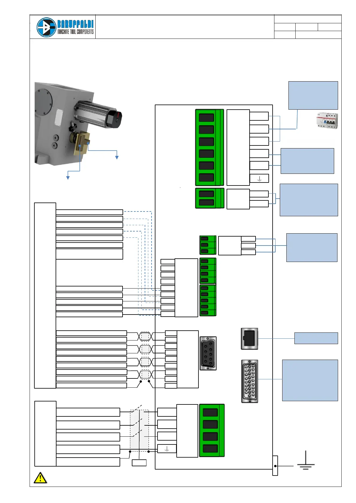
Power supply
230Vac +10/-15%
400Vac +10/-15%
Pmin =2KVA
(Shielded Cable)
Auxiliary supply
24Vdc ±10%
Circuit consumption is 500mA.
Total consumption depend of
relais/electrovalve
(Shielded Cable)
Electrovalve
Use auxiliary relays to
pilotate the electrovalve.
Imax Output=2,5A
(Shielded Cable)
I/O
Digital I/O connect to PLC.
Details at page N°6.
All signals are optoisolated.
After a short circuit is
necessary to switch
off the auxiliary supply
(Shielded Cable)
Black U Motor phase
Blue V Motor phase
Pink W Motor phase
Green-Yellow PE Motor phase
White C Shield
Yellow 1 Thermal switch
Yellow 2 Thermal switch
White-Red 3 ref
White-Yellow 4 0 ref
Black 5 0 cos
Red 6 cos
Yellow 7 sin
Blue 8 0 sin
Pink 9 Shield
LI.15
OP
LI.16
OP
+24v
OP
LI.12
LI.13
LI.14
Brown 10 +24V
Blue 11 0V
Black 12 Turret Unlock
Black 13 Turret Lock
Black 14 Zero Sensor
Brown 10 +24V
Blue 11 0V
Black 12 Turret Unlock
Black 13 Turret Lock
Black 14 Zero Sensor
Black A Live Tool Lock
Black B Live Tool Unlock
Turret Unlock
*The use of the Live Tool Locking signal is optional and up to
the user
LIVE TOOL TURRET VERSION
(Shielded cable)
TURRET
(Shielded cable - sensors 24Vdc no pnp LMax=200mA)
RESOLVER (Shielded Cable 4x(2x0.25mm²))
MOTOR (Shielded Cable (4x1.5mm²))
ELECTRICAL TERMINAL BLOCK - T1
ELECTRICAL TERMINAL BLOCK – T2
Do not install power contactor (or relais) on the input voltage of the drive (L1-L2-L3), it generates alarm on the drive.
For safety reasons it might be possible to put power contactor (or relais) on the phases between the motor and the drive (U-V-W), (e.g. to cut the power during
machine open door or emergency situation)
.
Protection device RCD (with differential
protection I
d
= 300mA) type F
+
Thermal magnetic circuit breake (16A)
type C
DB BUS (output)
DO NOT USE