INSTALLATION AND USE MANUAL
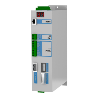
SERVO DRIVE TYPE – DB21
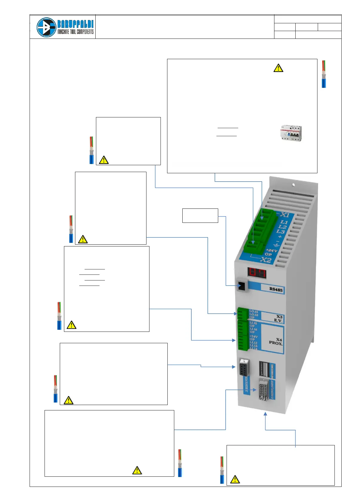
2. ELECTRICAL CONNECTIONS
X1 (INPUT)
POWER SUPPLY
Power net (L1-L2-L3)
Voltage option 1: 230Vac 3 phase +10/-15%
Voltage option 2: 400Vac 3 phase +10/-15%
Pmin power transformer (for input with 230V) 2KVA
4Arms / 16Arms peak Class S3
Size cable Ømin=1,5mm2
+ DB BUS OUTPUT - not is use
- DB BUS OUTPUT - not is use
Protection device RCD (with differential
protection I
d
= 300mA) type F
+
Thermal magnetic circuit breake (16A) type C
J1 (OUTPUT/INPUT)
DIGITALS INPUT/OUTPUT
Out 24Vdc x 100mA
In sink 24Vdc ≤5mA
Level H (min): 20VDC (typ.7mA@24VDC,
Vin(max)=30VDC Level L (max): 12VDC
D26sub connector pin used for dialogue
between plc and drives (details page 6)
X5 (OUTPUT)
MOTOR (U-V-W-T)
3 phase shielded cable Ømin=1,5mm2
with ground
J2 (INPUT)
ANGULAR POSITION TRANSDUCER
Use cable with shielded twisted pairs and
external shield Ømin=0,22mm2 up to 25m,
more than 25m: 0,50mm2.
We recommend to use only high quality
cable in order to prevent electromagnetic
noise issues
X4 (OUTPUT)
EXTRA PORTS
Li.15 – not is use
OP – not is use
Li.15 – not is use
OP – not is use
INDUCTIVE SENSORS
+24 Proximities supply (out)
OP Common (out)
Li.12 Unlocked turret prox.switch
Li.13 Locked turret prox.switch
Li.14 Zero proximity switch
X3 (OUTPUT)
ELECTROVALVES OUTPUT
Lo15 Unlocking command
Lo16 Locking command
OP Com 0V
24Vdc I
max 3A.
We recommend the use of auxiliary
relais for supply the solenoid valves
X2 (INPUT)
LOGIC SUPPLY
Pin (+24 OP)
24Vdc ±5% I
max 3A