INSTALLATION AND USE MANUAL
SERVO DRIVE TYPE – DB21
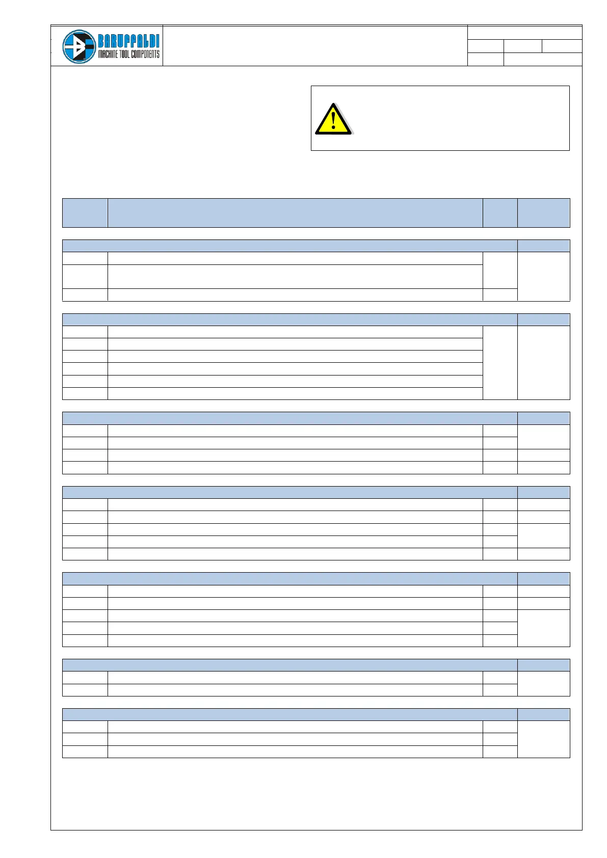
12. DRIVE ALARM
When malfunctioning occurs:
- are disabled the outputs ST INDEX, ST LOCK and
POSITION FEEDBACK
- the display shows the active alarm
- are activated the alarm bit in the J1 connector (binary coded)
Undervoltage (only with turret unlocked)
Voltage dipswitch selection (dipswitch n°6) has been
changed while the drive is ON
(A1.2) Failed attempt to save data in EEPROM
(A1.1) EEPROM contains altered data
(A2.0) Absolute sensor alarm
(A5.1) Radiator thermal alarm
(A6.0) Radiator thermal alarm
(A7.0) Auto calibration not completed
During unlocking the turret stays closed [Li.12=Off, Li.13=On]
No signal from unlock proximity switch [Li.12=Off, Li.13=Off]
Lock proximity switch in short circuit [Li.12, Li.13=On]
The unlock proximity switch signal has been lost during rotation [Li.12=Off]
During locking the turret stays unlocked [Li.12=On, Li.13=Off]
No signal from lock proximity switch [Li.12=Off, Li.13=Off]
Unlock proximity switch in short circuit [Li.12, Li.13=On]
The lock Px switch signal has been lost during work (turret indexed) [Li.13=Off]
Turret not locked at the start up [Li.13=Off]
A non-existing position has been called
Zero search in operative mode different from 1
In the table the CODE field is the sum of all bits
of alarm active.
Example: All.7.0 Time out rotation
Code 7, on connector J1 will be activated the
output: Lo.6 (1), Lo.7 (2), Lo.8 (4) = 1 +2 +4 = 7