Operating Instructions
Level measurement
CleverLevel
®
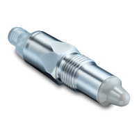
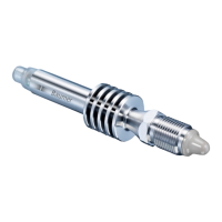
PL20H/S
Adaptive trigger – hygienic/industrial
Step 2: Selecting the trigger type
f
For the switch selected in step 1, select the
trigger type by holding the screwdriver on the
qTeach area again. When the desired trigger type
appears, remove the screwdriver:
White: Window trigger
Green: Adaptive trigger
If the LED ashes red, an error has occured and the
changes are not saved.
f
To restart the conguration, disconnect and
reconnect the sensor to the power supply.
Conguration via remote teach
Sensors that are installed in inaccessible locations
can be easily congured via remote teach. Via
remote teach, the different trigger types can be
set for SW1 and SW2. The switch logic is normally
open (NO) for both SW1 and SW2.
Note: Remote teach has to be activated with
FlexProgram. The conguration is only possible
during the rst 5 minutes after connecting the
sensor to the power supply. Within the 5 minutes,
the switch being congured does not work.
9 The remote teach function is activated on either
SW1 or SW2 with FlexProgrammer 9701 before
the integration of the sensor.
f
Short-circuit the switch output which has remote
teach activated with GND (0 V).
The LED rapidly blinks magenta.
f
Continue as described in „Conguration via
qTeach“, step 1 and 2.
Instead of a screwdriver, use the GND.
Conguration via FlexProgrammer 9701 and
PC
Switch points, hysteresis, damping, output mode,
etc. can be congured via FlexProgram and
FlexProgrammer 9701. Furthermore, a visualization
of the measured value can be displayed by using
the online measurement in FlexProgram.
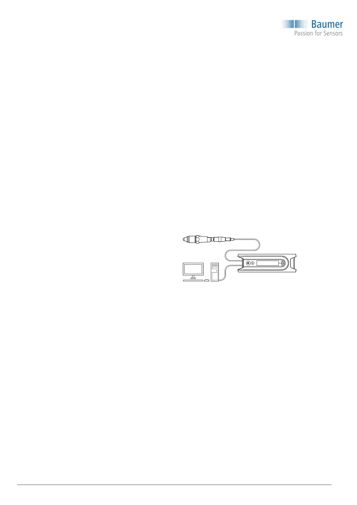
f
Connect the FlexProgrammer 9701 to the
sensor:
M12 plug version: Connect with the black head
M12 plug.
Cable version: Connect with crocodile clips.
Connect the red clip to Pin 1 (+Vs) and the
black clip to Pin 3 (GND).
f
Connect the FlexProgrammer 9701 to a PC with
FlexProgram installed.
f
Set parameters (refer to the HELP menu in
FlexProgram for more information).
Conguration via IO-Link master
Switch points, hysteresis, damping, output mode,
etc. can be congured through an IO-Link master.
f
Connect IO-Link master to sensor.
f
Connect IO-Link to PC and set parameters.
For a detailed description of the parameter and
process data for the IODD, refer to the product
page on www.baumer.com.
10 / 44
www.baumer.com