Min. impulse interval 30 ms
(Programming line 29, 30)
Input resistor 3.3 kΩ
Pegel low 0...1.6 V
Pegel high 14…27 V
Terminal 15 Main counter stop, time meter on,
hold (programming line 40)
Min. impulse interval Main counter stop 10 ms
Input resistor 3.3 kΩ
Stage low 0...1.6 V
Stage high 14…27 V
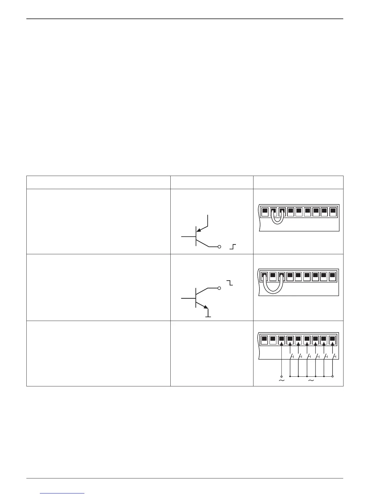
Programming input logic
The signal input logic can be programmed by means of a bridge bet-
ween terminals 18, 19 and 20, in accordance with the table below.
To be used Sensor signal Terminal assignment
- If the pulse generator is not supplied by
the sensor powersupply from the counter.
- If the pulse generator has a push-pull or
PNP output stage.
- If several counters are triggered in paral-
lel by a single pulse generator.
PNP, triggered by a
plus signal.