43
3.4.1 Typical connections
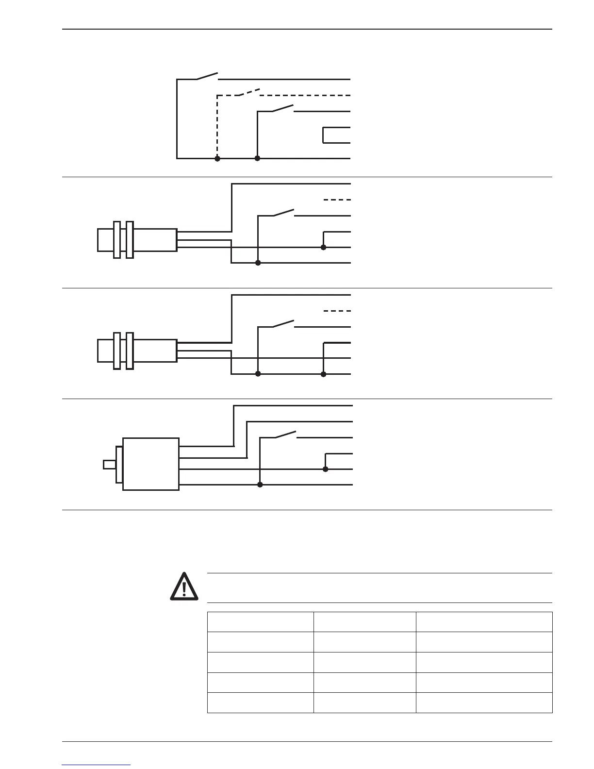
Pulse device Counter terminal assignment
Contact
(switched to plus)
12 track A
13 track B
14 reset
18 PNP (jumper to 0V)
19 0V
20 +24V
Proximity switch PNP 12 track A
13 track B
14 reset
18 PNP (jumper to 0V)
19 0V
20 +24V
Proximity switch NPN 12 track A
13 track B
14 reset
18 NPN (jumper to +24V)
19 0V
20 +24V
Incremental encoder with
PNP or push-pull output
12 track A
13 track B
14 reset
18 PNP (jumper to 0V)
19 0V
20 +24V
3.5 Connecting the sensor supply
Connect the sensor supply at terminals 19 and 20 – for example en-
coder supply, etc.
Do not use the sensor supply to supply non-earthed inductive or
capacitive loads. The sensor supply is not short-circuit proof.
Voltage supply Sensor supply Current load
24 VAC 12...26 VDC 80 mA
48 VAC 12...26 VDC 80 mA
85...265 VAC 24 VDC ±20 % 200 mA
24 VDC ±10 % 24 VDC ±20 % 200 mA