3.1 Connecting the voltage supply
Three voltage supply are available:
AC voltage: 24/48 VAC (50/60 Hz), set the required alternating vol-
tage with the voltage selector switch.
AC voltage: 85...265 VAC (50/60 Hz), wide range supply
DC voltage: 24 VDC ±10 %
Supply voltage Recommended external protection
24 VAC ±10 % M 400 mA
48 VAC ±10 % M 400 mA
85...265 VAC M 315 mA
24 VDC ±10 % M 500 mA
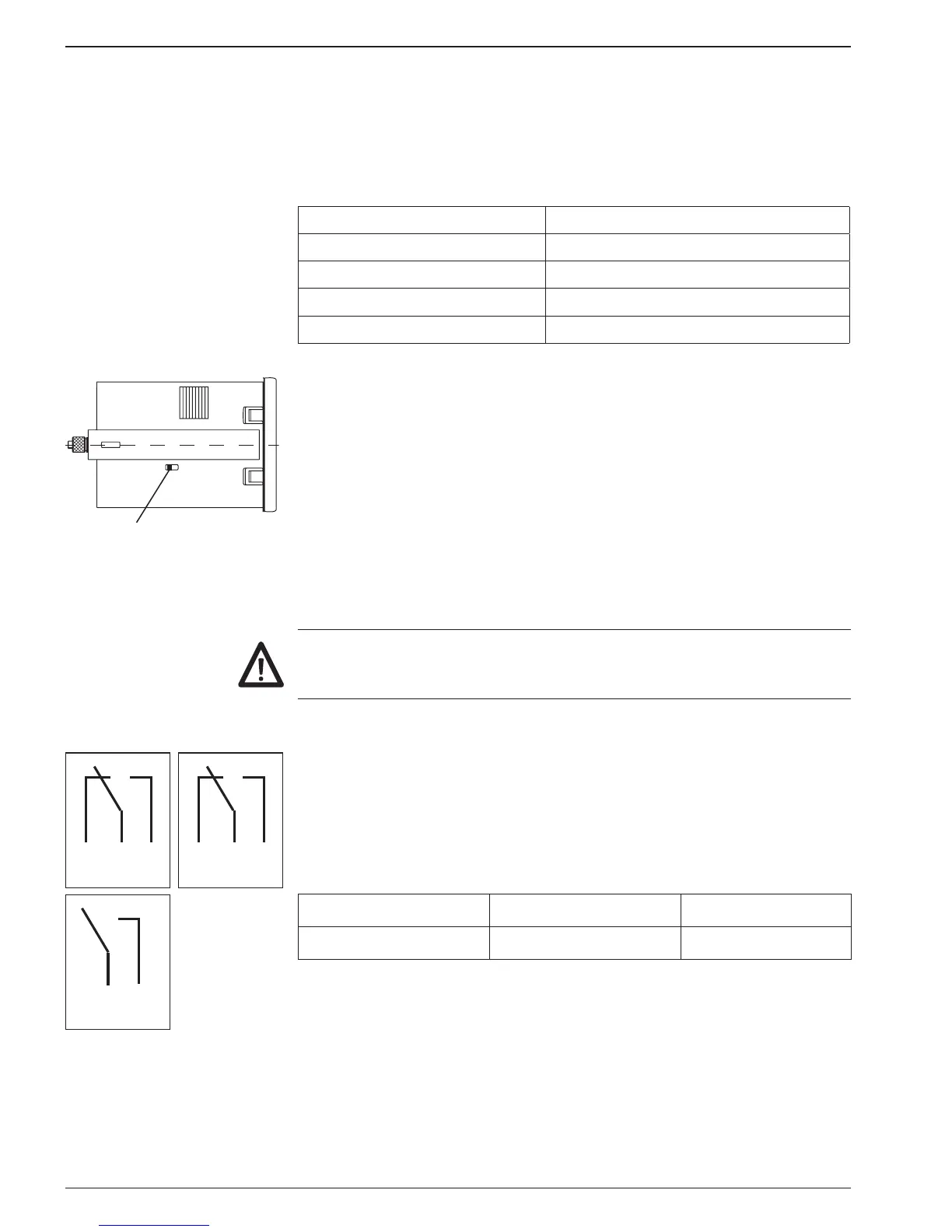
voltage selector
➜ Model 24/48 VAC: set the required alternating voltage with the
voltage selector switch.
➜ Connect AC at the contacts 2 and 3 according to the terminal
diagram.
DC-voltage 24 VDC
Connect voltage supply that is free from any interference. Do not uti-
lize the voltage supply for parallel supply of drives, shields, magnetic
valves, etc. Supplying lines must be separated from lines providing
load current.
Fire protection: Operate the instrument using the recommended
external fusing indicated in the type label. EN 61010 specifies that 8
A/150 VA (W) must never be exceeded in the event of a fault.
3.2 Assignment signal output „relay contact“
6 5 49 8 7
11 10
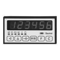
Terminals 4, 5, 6 and 7, 8, 9 are no-potential changeover contacts.
Terminals 10 and 11 are configured as NC or NO contacts in ac-
cordance with the purchase order specification. The signal outputs
can be assigned in accordance with the adjoining wiring diagram.
Implementation as a pulse or continuous signal, together with the
pulse time, is effected in the programming mode (lines 31, 32, 33).
Max. rating Max. voltage Max. current
150 VA/30 W 265 V 1 A