NE214
www.baumer.com
31
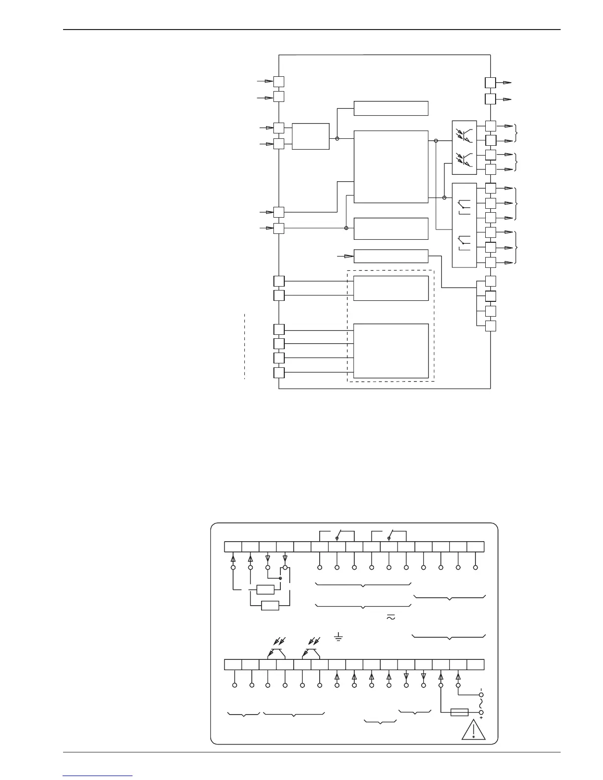
2.2 Block diagram
TxD+
TxD-
RxD+
RxD-
TxD
RxD
GND
RS232
RS422
Signal input
A
B
Reset
Stop/Hold
A 90° B
Totalizer
Operating time
meter
Analog output
Main counter with
2 presets
start count
scaling factor
P2
Output
P1
P2
Analog output
0(2) - 10 V
0(4) - 20 mA
2
3
4
5
6
7
8
9
10
11
12
13
20
21
22
23
24
25
30
27
28
29
Sensor
supply
+
-
P1
T,R-
T,R+
Interface
RS232 or
RS232
Interface
RS485
14
15
16
17
18
19
Voltage
supply
+
-
3 Connecting
This section first describes the terminal assignments, followed by
some typical connections.
Sections 3.1 to 3.5 contain specific instructions and the specifica-
tions for the individual terminals. The two inputs and outputs are as-
signed to two plug-in screw terminals. The two 15-pole screw-type
terminals are coded to prevent reversed polarity.
Assignment
Output
P1P2
P2 P1
Output
Stop
Reset
Track B
Track A
Count
+24V
0V
Sensor
supply
Br
RU
RI
Voltage supply
2367891415
16171819
10111213
202122232425
45
27282930 26
(+)
(-)
1
RS485
RxD-
RxD+
TxD-
TxD+
max. 250 V
terminal - terminal /
- terminal
GND
RxD
TxD
RS422
RS232
T,R+
T,R-