EasyManuals Logo

Baumuller DSD2 Series User Manual

Baumuller DSD2 Series
34 pages
To Next Page IconTo Next Page
To Previous Page IconTo Previous Page
Page #23 background imageLoading...
Page #23 background image
TAM 00699 23
DSD2 045 132 04/2018
Three-phase synchronous motor English
8.4 Main and control connection via combination-mounting-box (customer specific
design)
This combination- mounting-box is generally mounted on the end plate on NDE-side. The box is
90 °angulated and contrary to the standard design of the motors not turnable.
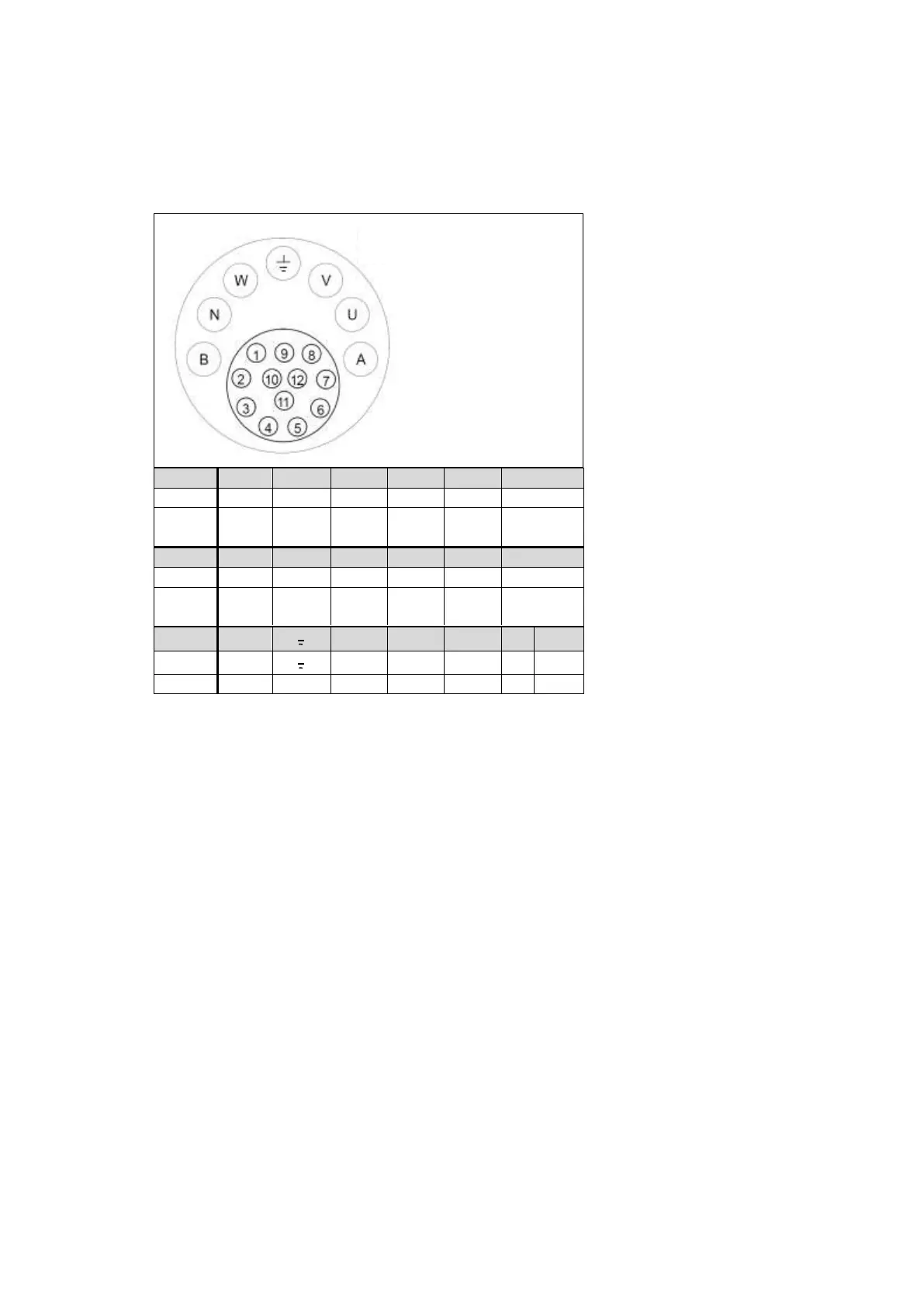
Figure 5: pole assignment of the combination-mounting-box
Outside section: Pin „B to A“ shows the pole assignment for the power terminal and PE-brake.
Inside section: Pin „1 to 12“ shows the pole assignment for resolver and thermal sensor.
Pin
1
2
3
4
5
6
Signal
Sin 1
Sin 2
/
/
/
shield
Colour
LTN
yellow
blue
Pin
7
8
9
10
11
12
Signal
Ref 1
K+
K-
Ref 1
Cos 1
Cos 2
Colour
LTN
black /
white
yellow
black
red /
white
red
black
Pin
B
U
V
W
N
A
Signal
Br. -
U
V
W
Br. +
Colour
black
red
Contact side
mounting box

Table of Contents

Questions and Answers:

Question and Answer IconNeed help?

Do you have a question about the Baumuller DSD2 Series and is the answer not in the manual?

Baumuller DSD2 Series Specifications

General IconGeneral
BrandBaumuller
ModelDSD2 Series
CategoryEngine
LanguageEnglish

Related product manuals