TAM 00699 20
DSD2 045 – 132 04/2018
Three-phase synchronous motor English
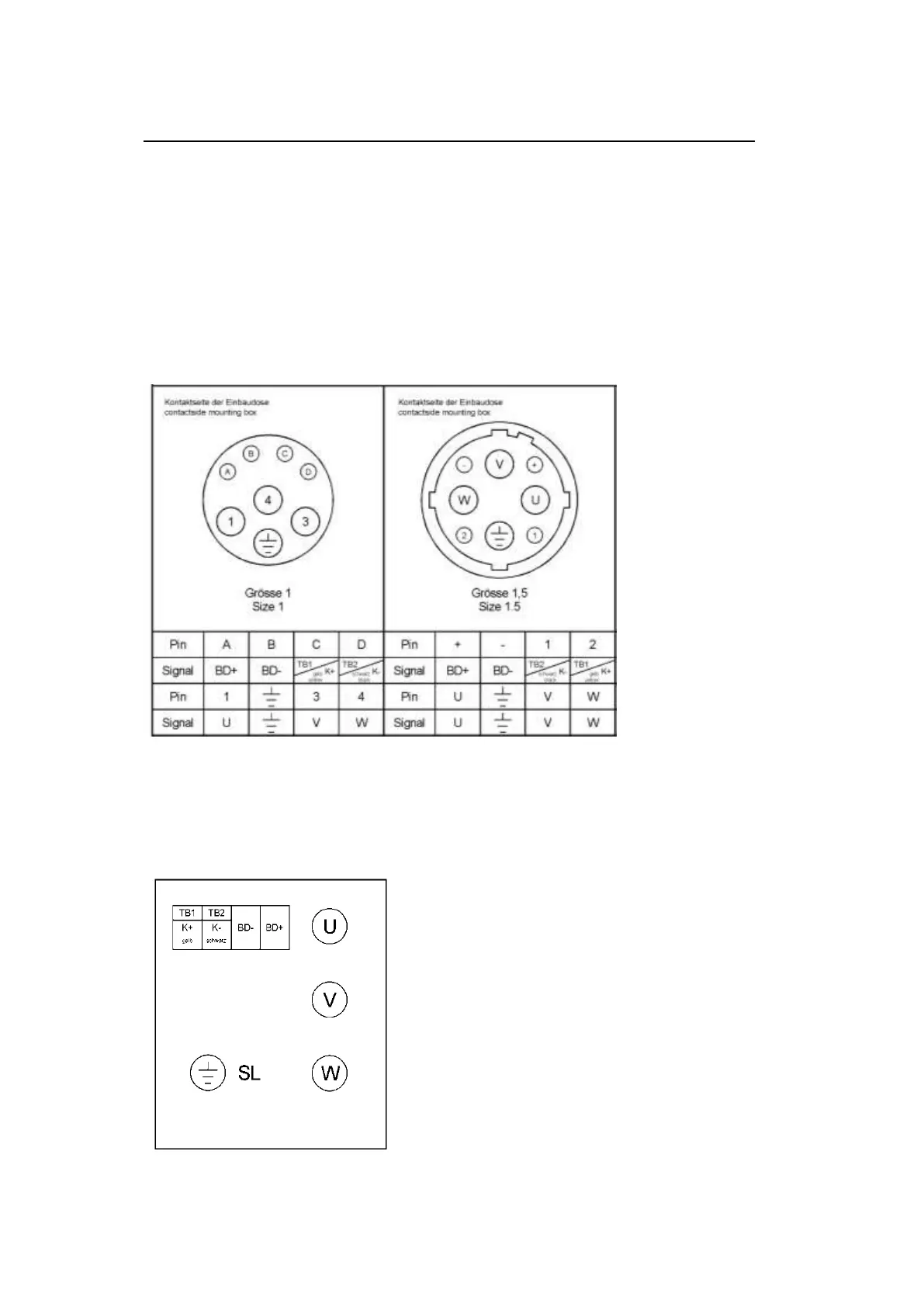
8 Appendix 1: pole assignment (main connection and Control terminal)
Key:
- U; V; W Power connection
- K+ / K- Temperature sensor (KTY84-130)
- R1 / R2 Temperature sensor (PT 1000)
- BD+ / BD- Brake
- SL Earth conductor
8.1 Main connection via plug
The standstill current I
0
of the motor determines the size of the built-in box.
Size 1: I
0
to 20 A Size 1.5 I
0
to 36 A
Figure 2: Main connection with thermal sensor and brake
Note: If the temperature sensor is wired ideally via the encoder cable, then the signals K+ and K-
are omitted in the above diagrams.
8.2 Main connection via the terminal box (Standard design acc. to catalogue)
Use during standstill current I
0
> 36 A.
Figure 3A: pole assignment with thermal sensor and brake at motor sizes of 56 to 100