24
9.0 Installation
© Baxi Heating UK Ltd 2017
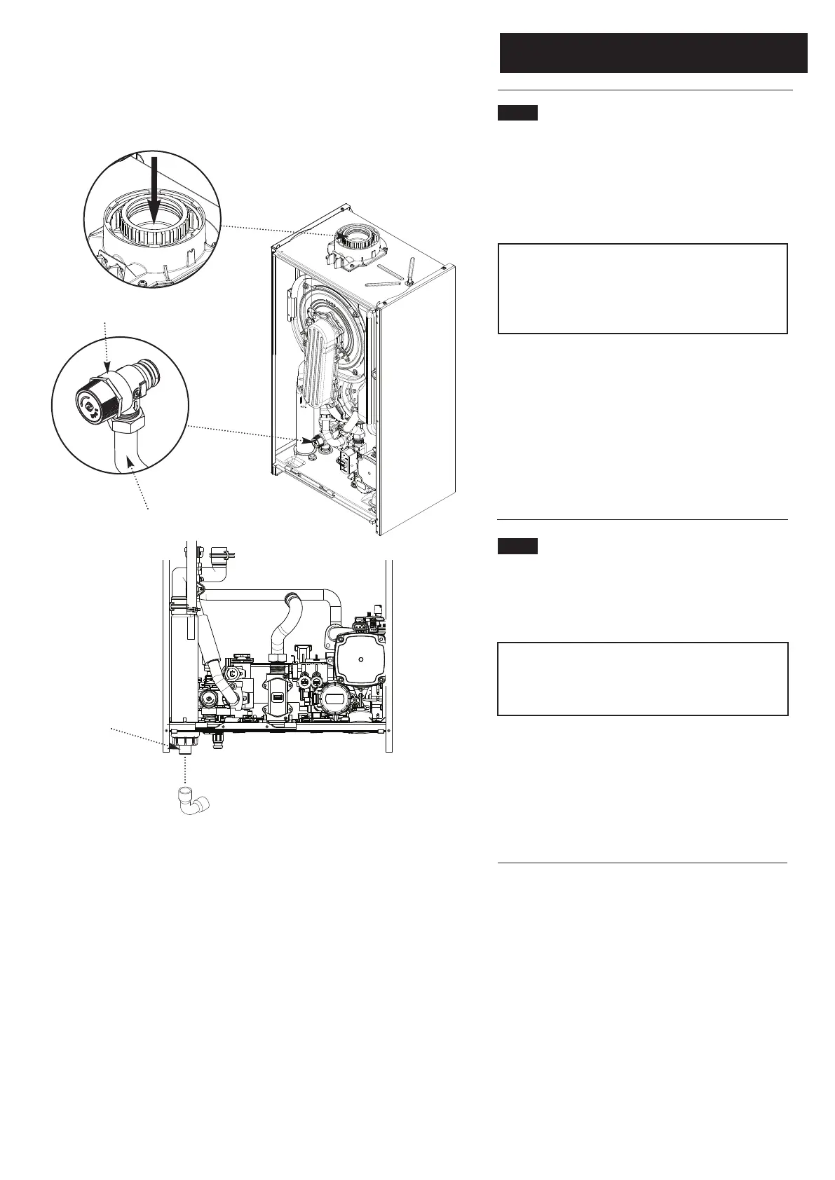
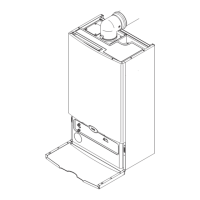
Fig. 22
Pressure Relief Valve
Discharge Pipe
Control Box removed
for clarity
9.4 Fitting the Pressure Relief Discharge Pipe
(Fig. 22)
1. Remove the discharge pipe from the kit.
2. Determine the routing of the discharge pipe in the vicinity
of the boiler. Make up as much of the pipework as is
practical, including the discharge pipe supplied.
IMPORTANT: Make all soldered joints before connecting
to the pressure relief valve. The relief valve is intentionally
angled to the right of the boiler. DO NOT adjust the
position of the valve. The discharge pipe must be installed
before pressurising the system.
3. The pipework must be at least 15mm diameter and run
continuously downwards to a discharge point outside the
building. See section 6.7 for further details.
4. Utilising one of the sealing washers, connect the discharge
pipe to the adaptor and tighten the nut hand tight, plus 1/4
turn to seal.
5. Complete the discharge pipework and route it to the
outside discharge point.
9.5 Condensate Drain (see section 7.7) (Fig. 23)
1. Using the elbow supplied, connect the condensate drain
pipework to the boiler condensate trap outlet pipe. When
connecting the elbow, ensure that the condensate sump is
not inadvertently unscrewed.
Ensure the discharge of condensate complies with any
national or local regulations in force (see British Gas
“Guidance Notes for the Installation of Domestic Gas
Condensing Boilers” & HHIC recommendations).
2. The hose will accept 21.5mm (
3
/
4
in) plastic overflow pipe
which should generally discharge internally into the
household drainage system. If this is not possible, discharge
into an outside drain is acceptable.
3. The boiler condensate trap should be primed by pouring
approximately 300ml of water into the flue spigot (Fig. 22a).
Do not allow any water to fall into the air inlet.
Condensate Trap
Outlet Pipe
Fig. 23
Prime Trap by pouring
300ml of water into
flue spigot
Fig. 22a