40
13.0 Changing Components
© Baxi Heating UK Ltd 2017
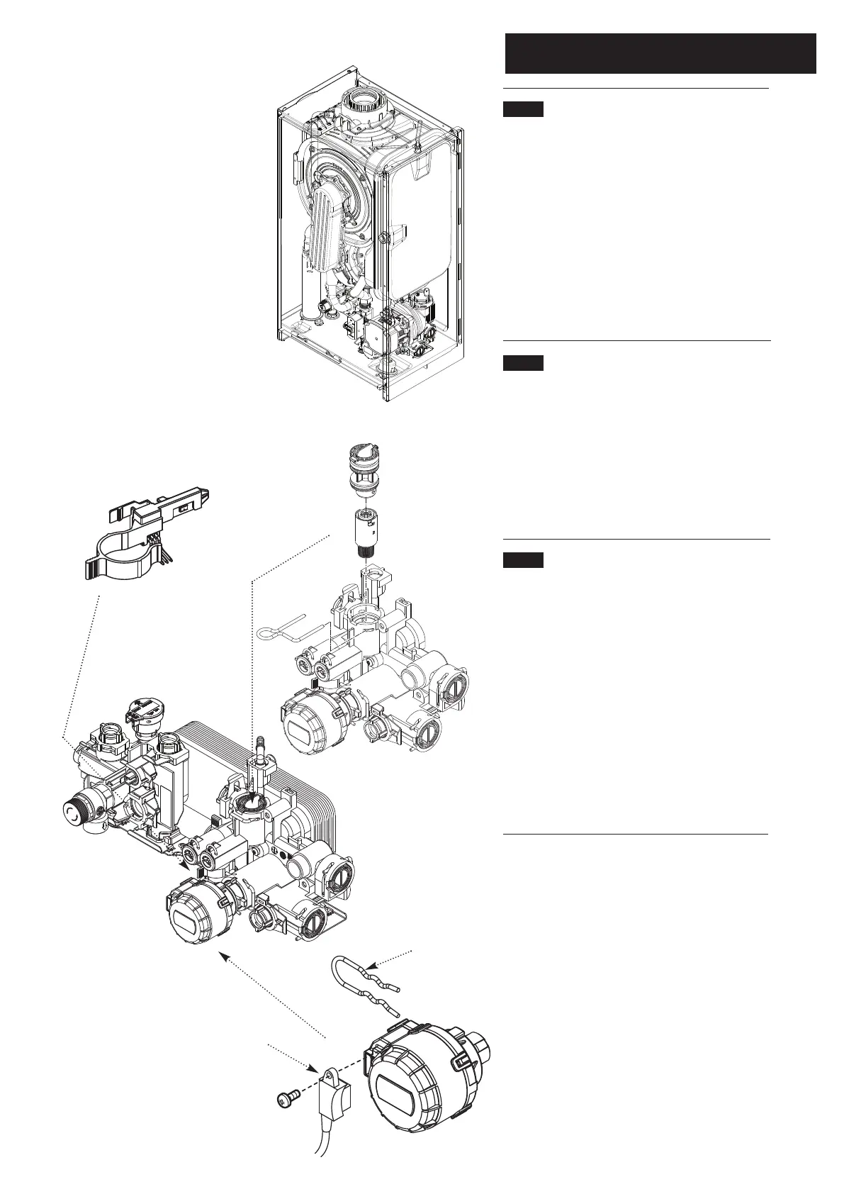
13.16 DHW Flow Regulator & Filter (Fig. 64)
1. Remove the Fan & Collector (13.2). Close the cold
mains inlet and draw off any residual DHW.
2. Pull out the securing clip and prise the regulator and
filter assembly out of the hydraulic inlet assembly.
3. Twist the body to unlock the bayonet connection
and remove the regulator.
4. Examine and clean the filter, and reassemble in
reverse order.
13.17 DHW Flow Sensor (‘Hall Effect’ Sensor)
(Fig. 65)
1. Pull the sensor off the DHW inlet manifold.
2. Disconnect the plug from the sensor and connect it
to the new component.
3. Fit the new sensor, ensuring it is correctly oriented
and fully engaged over the manifold.
13.18 Diverter Valve Motor (Fig. 66)
1. Undo the screw securing the electrical plug to the
motor unit. Disconnect the plug.
2. For ease of access remove the pressure gauge and
sealing grommet from the boiler bottom panel.
3. Hold the motor in place against the spring pressure
of the valve and remove the securing clip.
4. Remove the motor.
5. When fitting the new motor it will be necessary to
hold the unit firmly while depressing the valve return
spring.
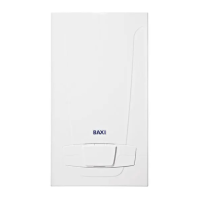
14.25
Pump, Gas Valve
Assemblies and Pipework
removed for clarity
DHW Flow Sensor
(‘Hall Effect’ Sensor)
DHW Flow
Regulator & Filter
Diverter Valve
Motor
Control Box removed
for clarity
Securing
Clip
Electrical Plug
Fig. 64
Fig. 65
Fig. 66