11
INSTALLER Section (en)
7710400 (01-06/18)
11.2 ACCESSORIES NOT INCLUDED IN THE SUPPLY
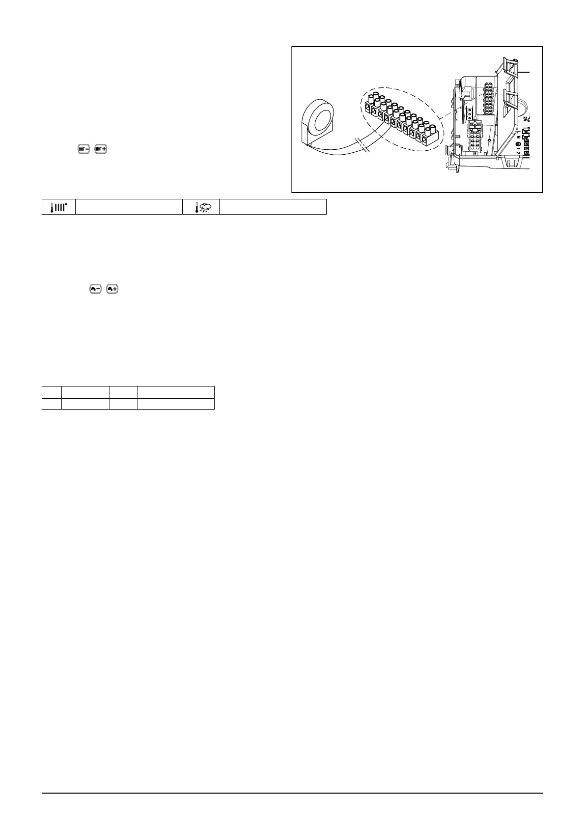
11.2.1 EXTERNAL SENSOR
To connect this accessory, see gure to side (terminals 4-5)
and the instructions supplied with the sensor.
SETTING THE "Kt" CLIMATE CURVE
When the external sensor is connected to the boiler, the
electronic board adjusts the ow temperature calculated
according to the set Kt coefcient. Select the required curve by
pressing
as indicated in the chart in annex SECTION
E for selecting the most appropriate one (00 to 90).
KEY TO CHART - “SECTION” E
Flow temp Outside temp
11.2.2 EXTERNAL STORAGE BOILER
The boiler can be electrically connected to an external storage boiler. A diagram of the hydraulic connection of the external
storage boiler is shown in annex "SECTION" F. Connect the DHW priority sensor NTC to terminals 9-10 on terminal block M2.
The sensitive element of the NTC sensor must be inserted in the special well located on the storage boiler. Make sure that the
exchange capacity of the storage boiler coil is appropriate for the power of the boiler. Adjust DHW temperature (+35°C...+60°C)
by pressing
.
IMPORTANT: set parameter P03 = 05 as described in section 14.
11.2.3 CONNECTING TO A ZONE SYSTEM
To use this function, install the programmable relay electronic board supplied as an accessory.
KEY TO ELECTRICAL CONNECTIONS (see diagram in annex "SECTION" G at the end of this manual).
Z Zone (1..n) EV Zone electrovalve
R Relay RT Room thermostat
The boiler can manage a zone heating system. The Room Unit (wall-mounted) can be used to control one zone while normal
ambient thermostats can be used to control the other zones.
SYSTEM CONNECTIONS
• Connect the zone 1 valve/pump to terminals 1 - 3 of the relay board terminal block inside the boiler control box.
• Connect the Ambient Thermostat contact of the other zones to terminals 1-2 of terminal block M1 (CONNECTING THE
AMBIENT THERMOSTAT section).
Check that parameter P04=02. Set parameter P10 (SETTING PARAMETERS section).
SIEMENS
QAC34
1
9
8
7
6
5
4
3
2
10
M2
CG_2394