9
INSTALLER Section (en)
7710400 (01-06/18)
10. INSTALLING THE FLUE
The boiler is easy and exible to install thanks to the extensive range of available
accessories, as described below. The boiler has been designed for connection to a
vertical or horizontal coaxial ue-air duct. The boiler can also be used with separate
ducts using the accessory splitting kit.
WARNINGS
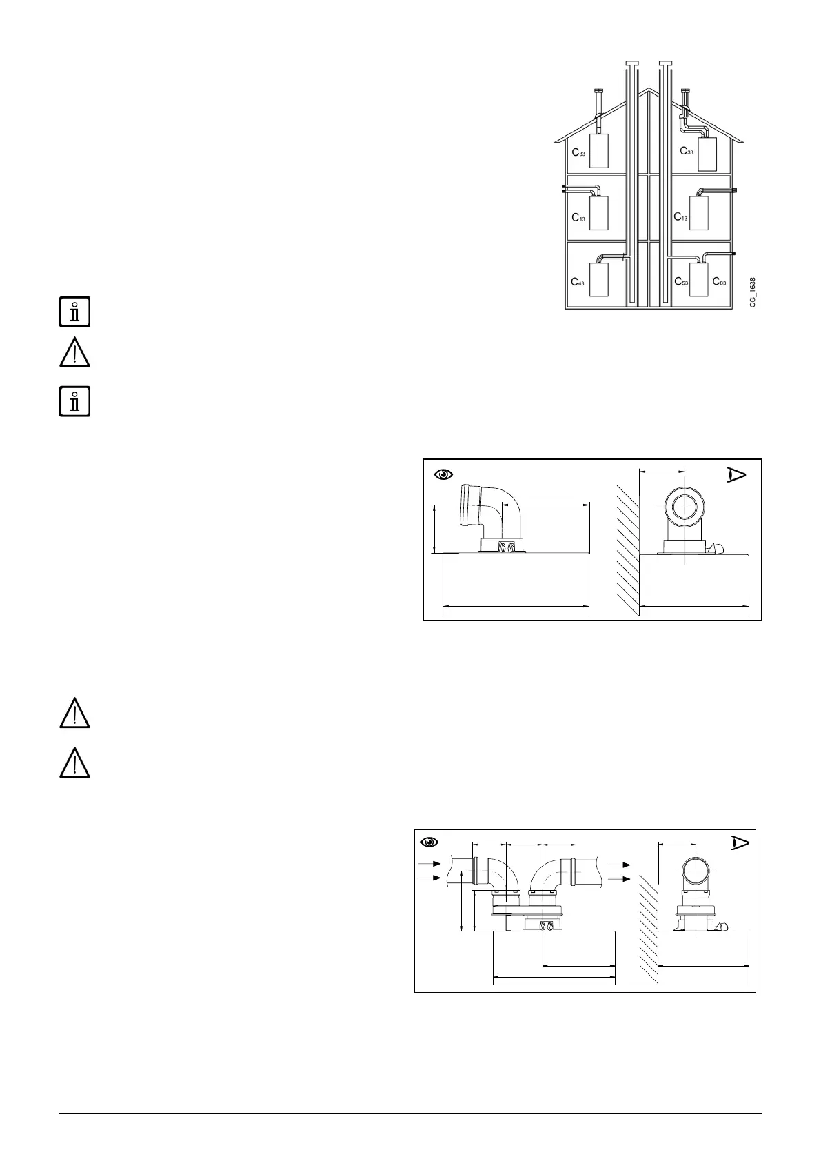
C13, C33 The terminals for separate ues must be tted inside a 50 cm square. Detailed
instructions are provided with the individual accessories.
C53 Do not t the ue and air duct terminals on opposite walls of the building.
C63 The pressure drop of the ducts must not exceed 100 Pa. The ducts must be certied
for this specic use and for a temperature in excess of 100°C. The ue terminal must be
certied to EN 1856-1.
C43, C83 The ue terminal or ue duct must be suitable for the purpose.
For optimal installation, the accessories supplied by the manufacturer should
be used.
To optimise operating safety, make sure the ue ducts are rmly xed to the wall with suitable brackets. The brackets must be
positioned over the joints at a distance of approximately 1 metre from one another.
SOME OUTLET DUCT INSTALLATION EXAMPLES AND THEIR RELATIVE MAXIMUM LENGTHS ARE SHOWN IN ANNEX
"SECTION" D AT THE END OF THIS MANUAL.
10.1 CONCENTRIC DUCTS
This type of duct is used to discharge exhaust fumes and draw
combustion air both outside the building and if a LAS ue is tted.
The 90° coaxial bend allows the boiler to be connected to a ue-
air duct in any direction as it can be rotated by 360° It can also
be used as a supplementary curve combined with a coaxial duct
or a 45° curve.
If fumes are discharged outside the building, the ue-air duct
must protrude at least 18 mm from the wall to allow an aluminium
weathering surround to be tted and sealed to avoid water
inltrations.
• A 90° bend reduces the total duct length by 1 metre.
• A 45° bend reduces the total duct length by 0.5 metres.
• The rst 90° bend is not included when calculating the maximum available length.
Secure the intake pipes with two galvanised screws with a diameter of 4.2 mm and a maximum length of 19 mm.
Before securing the screws, make sure that at least 45 mm of the pipe is inserted into the gasket (see the gures in annex
"SECTION" D at the end of this manual).
Make sure there is a minimum downward slope of 5 cm per metre of duct towards the boiler.
10.2 SEPARATE DUCTS
For special installations of the fumes inlet/outlet ducts, the
single splitting kit (C), supplied as an accessory, can be used.
This accessory, in fact, can be used to move the inlet and outlet
in any direction. This type of installation makes it possible to
discharge exhaust fumes both outside the building and into
single ue ducts. Comburent air can be drawn in at a different
location from that of the ue terminal. The splitting kit is xed
to the boiler turret (100/60 mm) and allows the comburent air
and outlet fumes to enter/leave the two separate ducts (80
mm). For further information, read the assembly instructions
supplied with the accessory.
The 90° bend is used to connect the boiler to the inlet and
outlet ducts, adapting them to various requirements. It can
also be used as a supplementary curve combined with a duct
or a 45° bend.
• A 90° bend reduces the total duct length by 0.5 metres.
• A 45° bend reduces the total duct length by 0.25 metres.
• The rst 90° bend is not included when calculating the maximum available length.