7710400 (01-06/18) 14
INSTALLER Section (en)
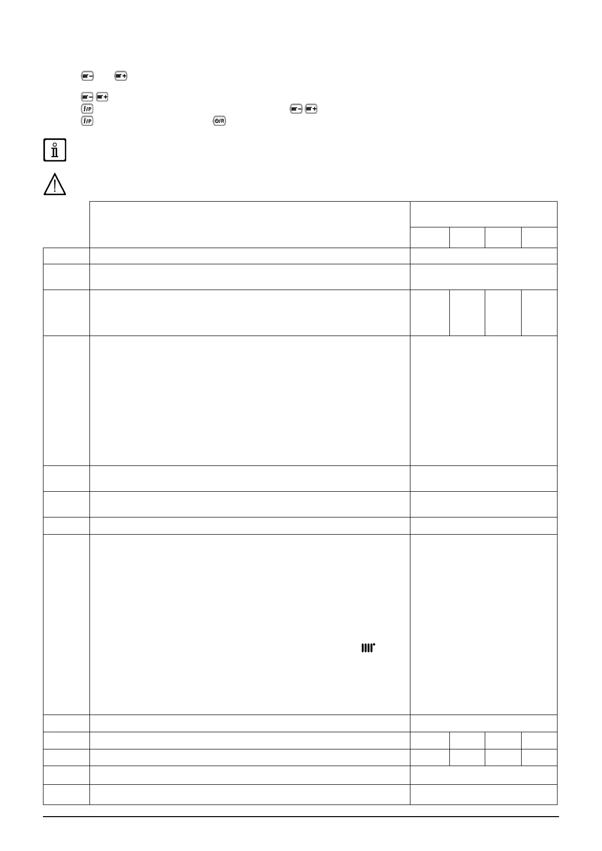
14. PARAMETERS SETTING
To programme the parameters of the boiler electronic board, proceed as follows:
• Press and together and hold them down for 6 seconds until programme row “P01” appears on the display alternated
with the set value;
• Press
to scroll the list of parameters;
• Press
the value of the selected begins ashing, press to change the value;
• Press
to conrm the value or press to exit without saving.
Further information concerning the parameters listed in the following table are supplied together with the required
accessories.
If the appliance is connected to an underoor system, set the parameter P16=01.
DESCRIPTION OF PARAMETERS
FACTORY SETTINGS
1.24 20 24 28
P01 Manufacturer information 01
P02
Gas used
00 = METHANE - 01 = LPG
00
P03
Hydraulic system
00 = instantaneous appliance
05 = appliance with external storage boiler
08 = heating only appliance
08 00 00 00
P04
Programmable relay 1 settings (See SERVICE instructions)
00 = no associated function
01 = relay contact closed with Room Thermostat demand (230V)
02 = relay contact closed with Remote Control demand (low voltage)
03 = system ll contact
04 = boiler faulty signal contact
05 = fan contact (kitchen fan)
06-07 = not used
08 = timed contact for enabling external DHW pump
09 = timed contact for enabling external DHW circulation pump via DHW programming
from remote control
10 = relay contact closed with DWH demand active
11 - 12 - 13 = not used
02
P05
Programmable relay 2 settings (See SERVICE instructions)
Same congurations as relay 1 - P04
04
P06
External probe input conguration
(See SERVICE Instructions)
00
P07..P09 Manufacturer information --
P10
Heating setpoint setting OT / RT
(Remote Control - Open Therm / Room Thermostat 230V~)
00=the temperature request is the Remote Control setpoint
01=the temperature Request is the highest setpoint between Remote Control and
PCB
02=the temperature request is the Remote Control setpoint. The Room Thermostat
enable the gas boiler operates
03= the calculated setpoint depends on the origin of the request (PCB or Remote
Control):
a)PCB (Ambient Thermostat): the setpoint is set by pressing the +/-
buttons
on the boiler control panel, after having rst disconnected the Remote Control from
the boiler.
b)Remote Control: the setpoint is set by modifying the “ULt” parameter (see Room
Unit accessory manual, chapter “INSTALLER FUNCTIONS”)
c)Simultaneous request PCB - Remote Control the higher setpoint of the two
requests is satised.
00
P11..P12 Manufacturer information --
P13 Max. heating output (0-100%) 100 80 80 86
P14 DHW max. output (0-100%) 100 80 100 100
P15 Min. heating output (0-100%) 00
P16
Maximum CH setpoint (°C)
00 = 85°C - 01 = 45°C
00