Fig. 17
8. Install 5/16-18 X1" gimlet screws in the flanges
of the mating sections around the oven
perimeter, both top and back.
NOTE: Start a few screws at several locations around
the flange to help align the flange holes.
9. Install all flange mating section screws and
insure mating surfaces are flush in the interior &
exterior of the oven before tightening the screws.
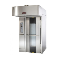
NOTE: If you have trouble aligning the mating holes
in the flange, you may have to manipulate the oven
sections using the levelers or by prying.
Fig. 18
Fig. 19
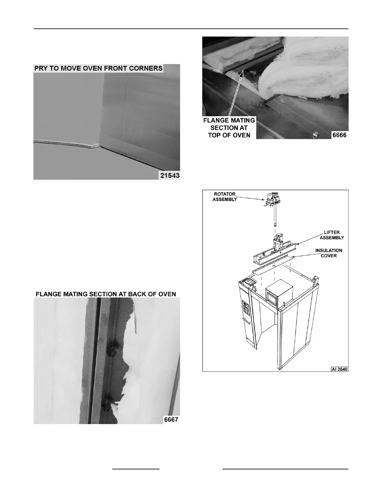
10. For OV500G1-EE & OV500E1 ovens only: Install
insulation cover onto top of oven.
11. For OV500G1-EE & OV500E1 ovens only: Install
rotator assembly onto lifter assembly.
Fig. 20
12. Install upper header support plate with #10 Tek
screws.
INSTALLATION INSTRUCTIONS
OV500-EE SERIES GAS RACK OVENS AND OV500 SERIES ELECTRIC RACK
OVENS - INSTALLING OVEN
F45469 Rev. D (1019) Page 20 of 49
NOTE: You may have to move oven front corners to
make the holes in the outer header align with the holes
in the oven.
 Loading...