TX1500 Manual Combined 1Oct03 PSC Page 6 of 31 Matrix
B-BUS CONTROL BUS
The Tx1500 ‘talks’ with all keyboards, alarm card and control interfaces via a polled 4 wire multidrop RS422
control bus named B-BUS.
All the units are equipped with standard RJ45 connectors allowing cat 5 patch cables to be used to connect over
short distances. On the larger sites RJ45 break out boxes are used to link between cat 5 cables and good
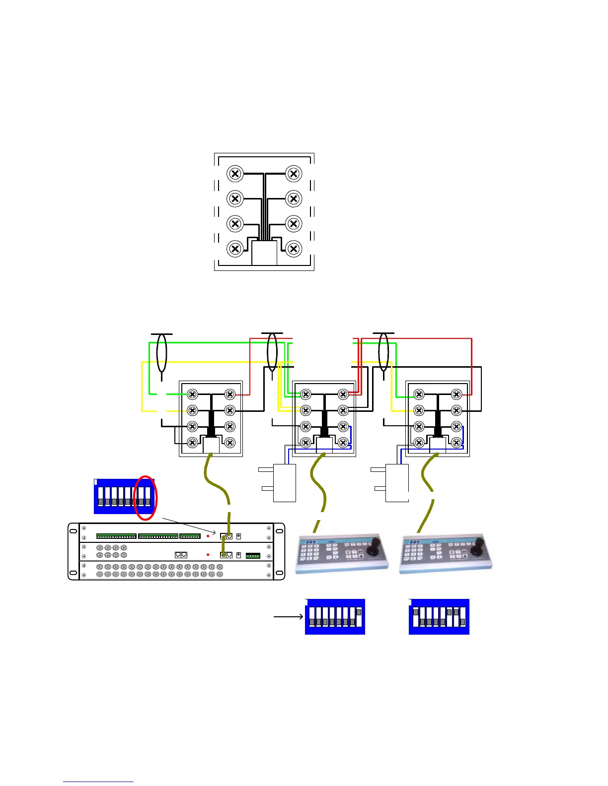
quality screen twin twisted pair data cable via screw terminals. The breakout box is as follows:
1 = DO NOT USE (+V)
2 = DO NOT USE (+V)
3 = RxA to MONITOR CARD
4 = TxA from MONITOR CARD
TxB from MONITOR CARD = 5
RxB to MONITOR CARD = 6
(0V) SCREEN = 7
(0V) SCREEN = 8
Fig 5. B-BUS - RJ45 breakout box connector, MONITOR CARD end of keyboard cable.
Fig 6. Keyboard BBUS wiring
Keyboard 1 is not at the end of line so BBUS termination is OFF (switch 6,7 OFF). It is addressed as 1 and the
PROGRAM key is enabled (switch 8 ON), allowing menu access and preset programming.
Keyboard 2 is at the end of the line so BBUS termination is ON (switch 6,7 ON). It is addressed as 2 and the
PROGRAM key is disabled (switch 8 OFF), preventing menu access and preset programming.
0V +12Vdc 0V +12Vdc
RJ45 patch cable max length = 2M
RJ45 patch cable max length = 2M
Rx Data (TO CPU)
Tx Data (FROM CPU)
RJ45 patch cable max length = 2M
BBUS maximum distance 1200M
Keyboard 1
BBUS Un-Terminated
Keyboard 2
BBUS Terminated
Alarm card
BBUS Un-Terminated
Switch 7-8 OFF
1 2 3 4 5 6 7 8
ON
Card 1 alarm 1-16
1 2 3 4 5 6 7 8
ON
1 2 3 4 5 6 7 8
ON
1-5 = Keyboard Address
6&7 = BBUS termination
8 = Program Key Enable
SCREEN
SCREEN
SCREEN