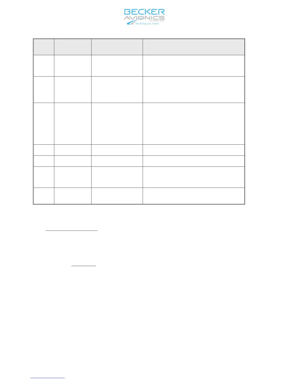
Ref. to
Fig. 3-1
Controls and
indicators
Description Function
C Button Push-button Push to jump from digit to digit for settings
or from one menu to the next;
generally used as an enter key
D IDT Push-button Activates the Special Identifier (SPI) i n ad-
dition to the reply code for a p p r o x . 18 se
-
conds; during this time “ID” appears i n the
LC display
E Display, part 1 2-line LCD display Displays the following informations:
- code indication in the top r o w
- flight level in the bottom r o w
- various informations in the bottom r o w
- additional indicators on the left s i d e (see
Ref. H)
F STO Push-button Stores the selected values to the settings
G SEL Push-button Opens and selects the menu
H Display
, part 2 LCD indicators Di s p l a y s additional indicators, (R for reply,
ID for Ident, ALT for XPDR A L T mode or ON
for XPDR ON mode, FL for f l i g h t level)
J VFR Push-button Activates VFR code in the upper row of the
display
3. Operating instructions
A. Switching on the unit (pre-flight check)
(1) Check that the circuit breaker is set and switch on the aircraft power
supply.
CAUTION: Do not switch on the transponder when engines are being
started or shutdown.
(2) Using mode switch (A), switch the transponder from OFF to SBY. A Po-
wer-on Built-In Test (PBIT) then follows automatically for 1 second.
Start-up see also section B.
INSTALLATION AND OPERATION BXP6401-X-(XX)
Page 3-2
34-50-08 September 2011
 Loading...