12
Installing the Oil Tank and Supply System
Fuel supply level with or above burner
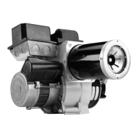
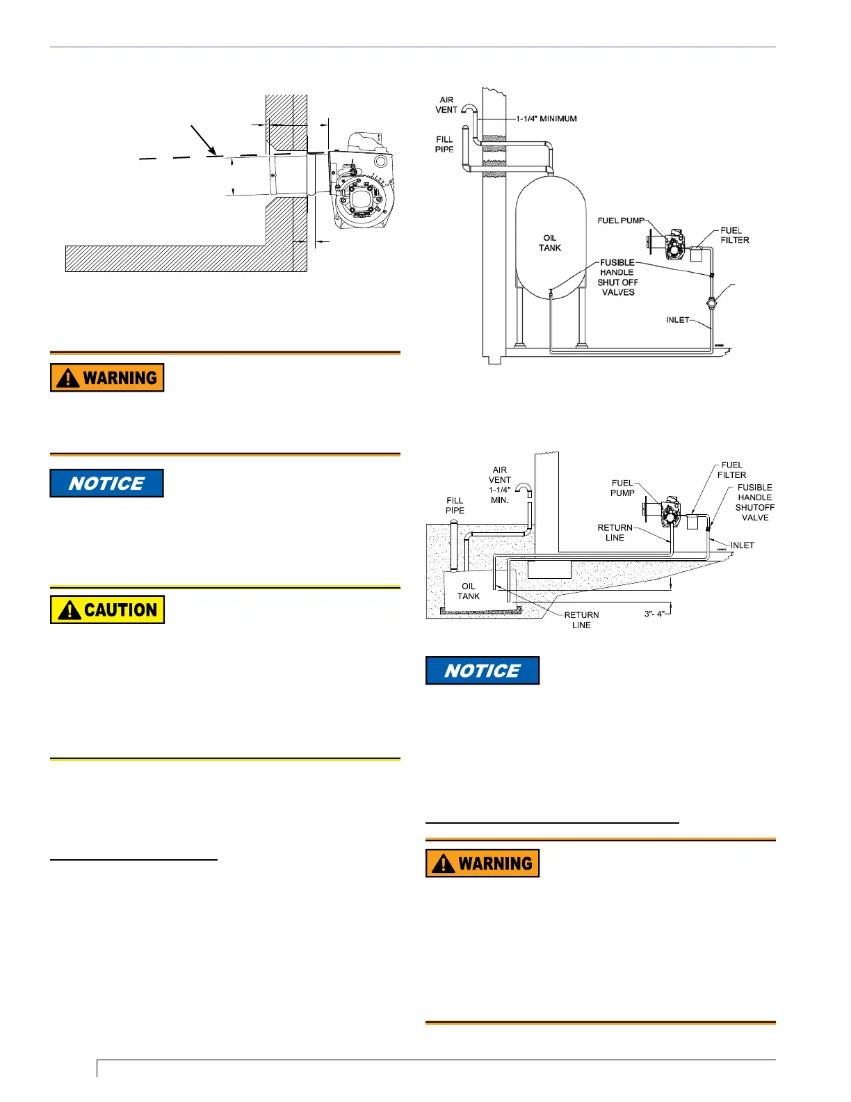
Figure 14. – Mounting Burner in Appliance Figure 15. – Inside Tank Gravity Feed System
Figure 16. – Outside Buried Tank-Lift System
Note: to determine the proper fuel line size, refer to the
fuel pump manufacturer’s instructions provided with
the burner. Refer to Figure 15 or Figure 16 for typical
installation layouts.
Fuel Line Valves and Filter
Install two high quality, oil duty rated, fusible handle design
shutoff valves in accessible locations on the oil supply line.
Locate one close to the tank and the other close to the
burner, upstream of the lter for service access. Refer to
NFPA 31 or the AHJ for further information regarding the
placement of oil safety valves in the fuel supply system.
Install a generous capacity lter inside the building between
the fuel tank shutoff valve and the burner, locating both the
lter and the valve close to the burner for ease of servicing.
Filter should be rated for 50 microns or less.
Section: Mount Burner on Appliance
Oil Leak and Fire Hazard
Install the oil tank following applicable standards in the U.S.
by referring to the latest edition of NFPA 31 or CSA-B139 &
CSA-B140 in Canada, and all authorities having jurisdiction.
y Never use Teon tape on fuel oil ttings.
y Tape fragments can lodge in fuel line components and fuel unit,
damaging the equipment and preventing proper operation.
y Use pipe joint sealant approved for use on kerosene, fuel oils
and biodiesel fuels
.
Damage to the pump could cause impaired burner
operation, oil leakage and appliance soot-up.
Do Not Use Teon Tape
To further protect the fuel supply
system and reduce nozzle orice
plugging with ring rates below 0.75 gph, a dual ltration
system can be installed. This typically consists of a 50
micron primary lter, located near the fuel tank and a
secondary lter rated for at least 10 microns located
near the burner.
y The burner is shipped without the by-pass plug
installed.
y Install the by-pass plug in two-pipe oil supply
systems ONLY.
Failure to comply could cause Immediate pump seal
failure, pressurized oil leakage and the potential for a
re and injury hazard.
Do Not Install By-pass Plug
with 1-Pipe System
SK8745
Tilt down 2
°
If space between burner air
tube and opening exceeds
1/2 inch, pack burner
opening with ceramic fiber
refractory.
4”
1/4”
A
7/8”
Fuel Supply System
Compatibility
The fuel supply system design and components must be
compatible with the fuel being used in the appliance. Follow all
guidelines and best practices recommended by the fuel supplier,
NFPA 30 & NFPA 31, and any state or local ordinances for safe
storage, ltering, conditioning, and delivery to the burner.
ANTI-SYPHON
VALVE
Carefully measure the insertion depth when using
an adjustable flange. Verify the insertion depth when
using a welded flange.
 Loading...