8
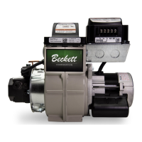
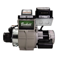
Prepare the Burner
Burner fuel unit
Verify that the burner fuel unit is compatible with the
oil supply system. For more details, refer to the pump
manufacturer’s instructions provided with the burner.
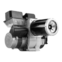
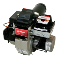
Attach air tube (if not already installed)
If using a ange and gasket, slide them onto the air tube.
Then attach the air tube to the burner chassis using
the four sheet metal screws provided. Please refer to
Installation Instruction sheet included with ange kit.
Nozzle and Pump Pressure
Install burner nozzle (if not already installed)
1. Remove the plastic plug protecting the nozzle
adapter threads.
2. Place a 3/4” open-end wrench on the nozzle
adapter. Insert the nozzle into the adapter and
nger tighten. Finish tightening with a 5/8” open-end
wrench. Use care to avoid bending the burner head
support legs or electrodes.
If you remove the head
to replace the nozzle (type “L1”/“L2” or “V1” heads),
carefully reconnect the head to the nozzle adapter,
making sure that the head support makes contact with
the nozzle adapter shoulder. Refer to Figure 11 or 12
Page 11.
3. If the nozzle is already installed, remove the nozzle
line assembly to verify that the nozzle size and
spray pattern are correct for the application (per
appliance manufacturer’s information). Verify that
the electrode tip settings comply with Figure 8,
Page 9.
4. If the nozzle is not installed, obtain a nozzle from
the manufacturer, having the capacity and spray
angle specied in the appliance manufacturer’s
information. For conversions or upgrades, when
information is not available for the application:
Section: Prepare the Burner
Use only nozzles having the brand, ow rate (gph),
spray angle and pattern specied by the appliance
manufacturer.
Follow the appliance manufacturer’s specications for
the required pump outlet pressure for the nozzle, since
this affects the ow rate.
y Nozzle manufacturers calibrate nozzle ow rates at
100 psig.
y When pump pressures are higher than 100 psig, the
actual nozzle ow rate will be greater than the gph
stamped on the nozzle body. (Example: A 1.00 gph
nozzle at 140 psig = 1.18 gph)
y Securely tighten the nozzle (90 torque inch pounds).
y For typical nozzle ow rates at various pressures
refer to Figure 6.
Incorrect nozzles and ow rates could
result in impaired combustion, under-
ring, over-ring, sooting, puff-back of
hot gases, smoke and potential re or
asphyxiation hazards.
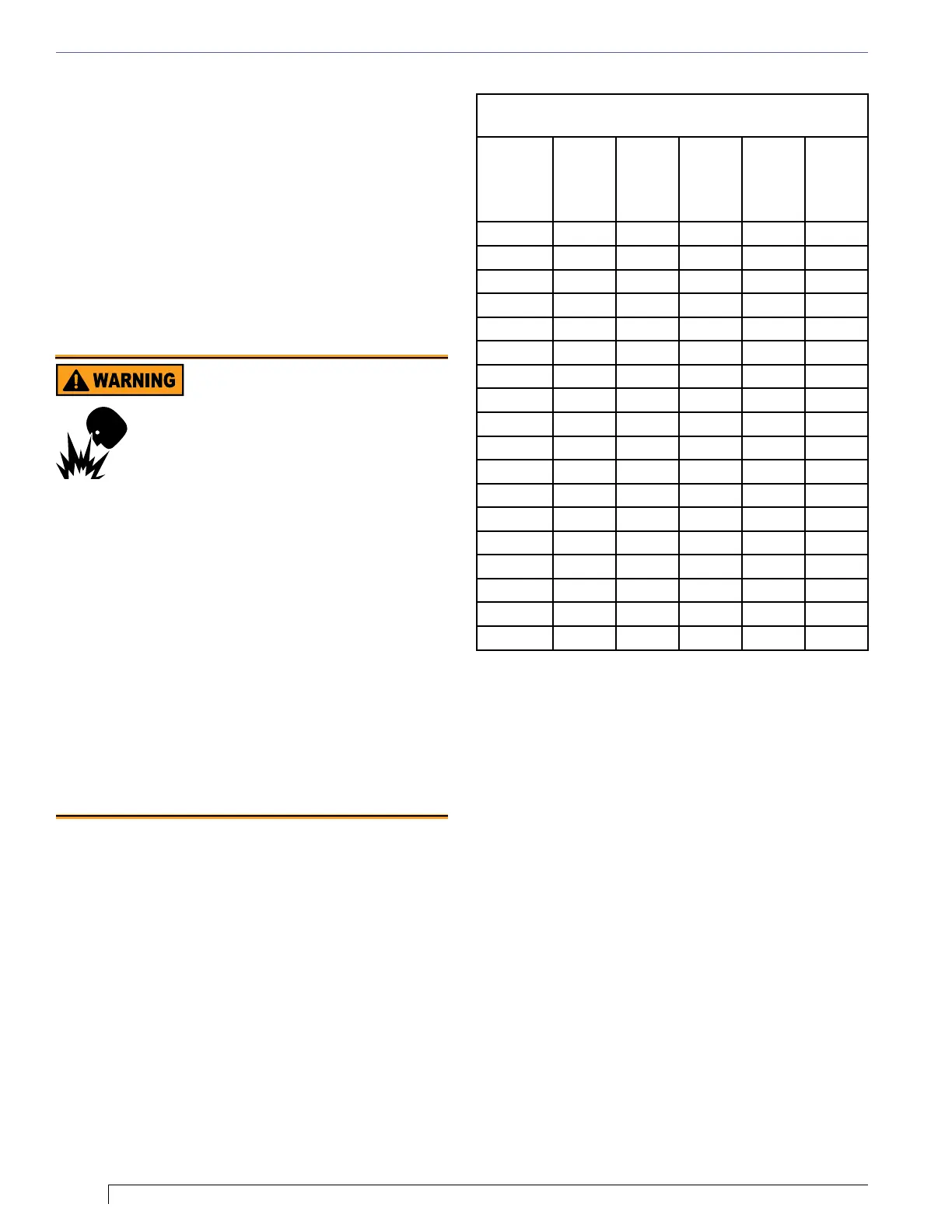
Correct Nozzle and Flow
Rate Required
Figure 6. Nozzle Flow Rate by Size
Nozzle ow rate U. S. gallons per hour of No. 2 fuel
oil when pump pressure (psig) is:
Nozzle
size
(rated at
100 psig)
125 psi 140 psi 150 psi 175 psi 200 psi
0.40 0.45 0.47 0.49 0.53 0.56
0.50 0.56 0.59 0.61 0.66 0.71
0.60 0.67 0.71 0.74 0.79 0.85
0.65 0.73 0.77 0.80 0.86 0.92
0.75 0.84 0.89 0.92 0.99 1.06
0.85 0.95 1.01 1.04 1.13 1.20
0.90 1.01 1.07 1.10 1.19 1.27
1.00 1.12 1.18 1.23 1.32 1.41
1.10 1.23 1.30 1.35 1.46 1.56
1.20 1.34 1.42 1.47 1.59 1.70
1.25 1.39 1.48 1.53 1.65 1.77
1.35 1.51 1.60 1.65 1.79 1.91
1.50 1.68 1.77 1.84 1.98 2.12
1.65 1.84 1.95 2.02 2.18 2.33
1.75 1.96 2.07 2.14 2.32 2.48
2.00 2.24 2.37 2.45 2.65 2.83
2.25 2.52 2.66 2.76 2.98 -
2.50 2.80 2.96 - - -
 Loading...