9
AFG Burner Manual
Figure 9. AFG Reduced Firing Rates (with LFRB)
Burner head type Low Firing Rate Bafe installed
F0 up to 0.65 gph
F3, L1, or L2 up to 0.85 gph
F4 or F6 up to 0.90 gph
V1 up to 1.00 gph
○ Refer to Figure 7 to select the mid-range nozzle
spray angle for the head type being used.
○ Fire the burner and make sure the combustion
is acceptable and the ame is not impinging on
chamber surfaces.
○ If a shorter ame is needed, select a wider spray
angle. If a longer ame is needed, select a
narrower spray angle.
○ Either hollow or solid spray patterns may be used.
If combustion results are not satisfactory with the
selected spray pattern, try the other pattern.
Mount Burner on Appliance
Mounting options
1. Bolt the burner to the appliance using the factory-
mounted ange or an adjustable ange.
Mounting dimensions
1. When using the Beckett universal adjustable ange,
mount the air tube at a 2° downward pitch unless
otherwise specied by the appliance manufacturer.
2. Verify that the air tube installed on the burner
provides the correct insertion depth. See Figure 14,
page 12.
3. The end of the air tube should normally be ¼” back
from the inside wall of the combustion chamber.
Never allow the leading edge of the head assembly
to extend into the chamber, unless otherwise
specied by the heating appliance manufacturer.
Carefully measure the insertion depth when using
an adjustable ange. Verify the insertion depth
when using a welded ange.
Figure 7. Nozzle Spray Angles
Recommended nozzle spray angles
“F” head 70° or 80° nozzle
“L1” & “L2” head 45°, 60°, or 70° nozzle
“V1” head 45°, 60°, or 70° nozzle
The dimensions shown below are for use with L2 heads
and M series air tube combinations ending with an ‘N’
sufx (example: AFG70MDAQN)
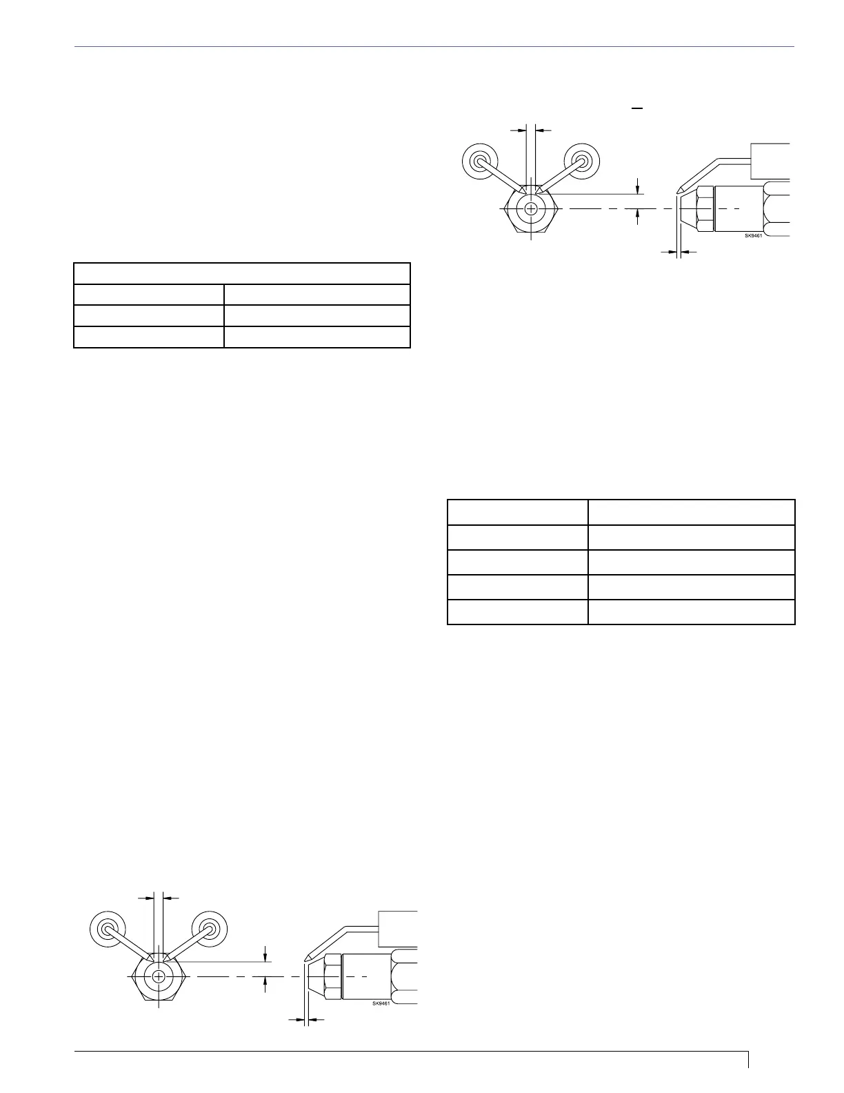
Check/adjust electrodes
Check the electrode tip settings. Adjust if necessary
to comply with the dimensions shown in Figure 8. To
adjust, loosen the electrode clamp screw and slide/rotate
electrodes as necessary. Securely tighten the clamp
screw when nished.
Servicing nozzle line assembly
1. Turn off power to burner before proceeding.
2. Disconnect oil connector tube from nozzle line.
3. Loosen the two screws securing igniter retaining
clips and rotate both clips to release igniter
baseplate. Then tilt igniter back on its hinge.
4. Remove splined nut.
5. “F” head air tube. - Remove nozzle line assembly
from burner, being careful not to damage the
electrodes or insulators while handling. To ease
removal of long assemblies (over 9 inches), rotate
assembly 180° from installed position after pulling
partially out of tube.
6. “L1”, “L2”, and “V1” head air tubes. - Slide nozzle
line assembly forward (further into air tube) so the
head clears the venturi opening. Then rotate the
nozzle line assembly 90° so the nozzle line end
points up. Pull the nozzle line assembly toward you
and remove assembly from burner.
Section: Mount Burner on Appliance
Figure 8. – Electrode Tip Adjustment
Standard Dimensions for F, L1, and V1 Heads.
5/32” Gap
5/16” Above
Center
1/16” Nozzle-to-tip
Spacing
5/32” Gap
1/4” Above
Center
1/8” Nozzle-to-tip
Spacing
Low Firing Rate Bafe
The AFG Low Firing Rate Bafe (LFRB) reduces the
air ow and pressure. The LFRB is sometimes used for
ring rates under 1.00 gph as listed in Figure 9. Refer
to the appliance manufacturer’s instructions. Do not
omit the LFRB when specied. Omitting the bafe when
specied or installing the bafe when not specied could
result in impaired burner performance.
7. To replace the nozzle assembly, reverse the above steps
 Loading...