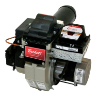
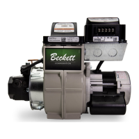
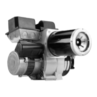
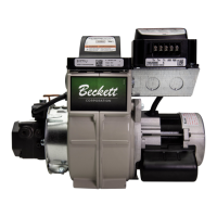
RWB 6104 WMNX Page 15
Loosen the two screws securing the rear door.
Swing the door to the right and down.
Loosen the splined nut.
Remove the nozzle line electrode and head
assembly from the burner by drawing it straight
back and out the rear door opening. The adjust-
ment mechanism is still attached. Be careful not
to damage the electrodes or insulators while
handling.
To replace the nozzle assembly, reverse the
above procedure.
Nozzle Installation
Perform the following steps when replacing a
nozzle.
5.
6.
7.
8.
•
Trained Service Technician’s Regular Maintenance
Remove the nozzle line assembly to gain ac-
cess to the nozzle.
Use a 3/4” open-end wrench to hold the nozzle
adapter. DO NOT attempt to remove or replace
the nozzle without securing the adapter, as
nozzle alignment could be seriously affected.
Do not squeeze the electrodes when handling
the nozzle line assembly. Excessive force could
change the electrode tip settings or damage the
ceramic electrode insulators.
Use a 5/8” open-end wrench to carefully remove
the existing nozzle.
Inspect the nozzle adapter before installing the
new nozzle. If it is grooved or scratched on the
sealing surface, replace the nozzle line assem-
bly. If the surface is damaged, oil could leak
at the nozzle to adapter joint, causing serious
combustion problems.
Protect the nozzle orifi ce and strainer when in-
stalling. If the orifi ce gets dirt in it or is scratched,
the nozzle will not function properly.
1.
2.
3.
4.
5.
6.
Use only nozzles having the brand, fl ow rate (gph), spray
angle and pattern specifi ed by the appliance manufactur-
er or Beckett Residential Burner OEM Spec Guide, Part
#6711.
Follow the appliance manufacturer’s specifi cations for the
required pump outlet pressure for the nozzle, since this
affects the fl ow rate.
Nozzle manufacturers calibrate nozzle fl ow rates
at 100 psig.
This burner utilizes pressures higher than 100
psig, so the actual nozzle fl ow rate will be greater
than the gph stamped on the nozzle body. (Exam-
ple: A 1.00 gph nozzle @ 140 psig = 1.18 gph)
For typical nozzle fl ow rates at various pressures see ac-
companying chart.
•
•
Incorrect nozzles and fl ow rates
could result in impaired combus-
tion, under-fi ring, over-fi ring, soot-
ing, puff-back of hot gases, smoke
WARNING
!
Correct Nozzle and Flow
Rate Required
and potential fi re or asphyxiation hazards.
Removing Nozzle Line for Service (Ref-
erence the Replacement Parts Diagram.)
•
Before proceeding, turn off the main power
switch to the burner.
Remove the burner cover by loosening the four
thumb screws (two on each side of burner).
Disconnect the copper connector tube assembly
from the nozzle line bulkhead fi tting.
Loosen the two screws securing the igniter re-
taining clips and rotate both clips to release the
igniter baseplate. The igniter should pop up and
be supported by the prop spring.
1.
2.
3.
4.
Use care when handling, removing and installing oil
nozzles.
Carefully follow the guidelines provided in this sec-
tion.
•
•
A damaged nozzle could cause impaired com-
bustion, sooting, puffback of hot gases, smoke,
oil leakage and potential fi re or asphyxiation
hazards.
Protect Nozzle from
Damage
!
CAUTION
Disconnect electrical power before installing or
servicing the burner.
Provide ground wiring to the burner, metal control
enclosures and accessories. (This may also be
required to aid proper control system operation.)
Perform all wiring in compliance with the Nation-
al Electrical Code ANSI/NFPA 70 (Canada CSA
C22.1)
•
•
•
Electrical shock can cause severe per-
sonal injury or death.
Electrical Shock Hazard
WARNING
!
 Loading...