Page 6 RWB 6104 WMNX
General Information
Table 2. – Burner Specifi cations
Capacity
LB & LC
Firing rate: 0.40 – 1.35 GPH
Input: 56,000 – 189,000 Btu
Capacity
LD & LF
Firing rate: 1.10 - 1.75 GPH
Input: 154,000 – 245,000 Btu/h
Fuels U. S No. 1 or No. 2 heating oil only
...........(ASTM D396)
Canada No. 1 stove oil or No. 2
.........furnace oil only
Electrical Power supply: 120 VAC, 60 Hz, single phase
Operating load: 5.8 Amps max
Motor: 1/7 hp, 3450 rpm, NEMA 48M
frame PSC rotation CCW
when facing shaft end
Ignition: Continuous duty solid-state igniter
Fuel pump Outlet pressure ...... Note 1
Air tube ATC code .......See Table 3
Dimensions
(with cover)
Height (maximum): 12-1/2 inches
Width (maximum): 15 inches
Depth: 9-1/4 inches
Air tube diameter: 3-1/4 inches
*
Note 1. See appliance manufacturer’s burner specifi cations for
recommended outlet pressure.
General Information
!
CAUTION
DO NOT USE GASOLINE, CRANK-
CASE OIL, OR ANY OIL CONTAINING
GASOLINE.
Certifi cations/approvals
Underwriters Laboratories has certifi ed this burner to
comply with ANSI/UL 296 and CSA-B139. Low sulfur
#1 and #2 fuel oils reduce heat exchanger deposits
with all burners compared to the standard fuels. Re-
duced deposits extend the service interval for cleaning
and improve the effi ciency of the appliance over time.
Low sulfur fuels reduce particulate and oxides of ni-
trogen emissions as well. The Oilheat Manufacturers’
Association recommends these fuels as the preferred
fuels for this burner.
Notice Special Requirements
THE INSTALLATION OF A BURNER SHALL BE
IN ACCORDANCE WITH THE REGULATIONS
OF AUTHORITIES HAVING JURISDICTION.
For recommended installation practices in the
U.S. refer to the latest edition of NFPA 31. (CSA-
B139 and CSA-B140 in Canada.
Concealed damage — If you discover damage
to the burner or controls during unpacking, notify
the carrier at once and fi le the appropriate claim.
•
•
•
•
Starting with minimum gph fi ring rate, the mini-
mum size recommended is 6” fl ue pipe with 8” X
8” inside chimney, unless specifi ed otherwise by
the appliance manufacturer.
1.
Carefully inspect the chimney or exhaust vent
system.
Make sure it is properly sized and in good work-
ing condition.
Follow the instructions supplied by the appliance
manufacturer.
The installation must strictly comply with all ap-
plicable codes, authorities having jurisdiction and
the latest revision of the National Fire Protection
Association Standard NFPA 31 for the installa-
tion of chimneys and vent sizing, (or CSA-B139
and CSA-B140 in Canada).
Regulation by these authorities take precedence
over the general instructions provided in this in-
stallation manual.
•
•
•
•
•
Fire, Smoke & Asphyxia-
tion Hazard
WARNING
!
Firing rate
(gph)
Head ATC codes for usable air tube
lengths:
(min-max) 5” 7” 9”
0.40-1.35 9-Slot NX50LB NX70LB NX90LB
0.40-1.35 6-Slot NX50LC NX70LC NX90LC
1.10-1.75 9-Slot NX50LD NX70LD NX90LD
1.10-1.75 6-Slot NX50LF NX70LF NX90LF
Table 3. – Air Tube Combinations (ATC)
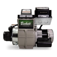
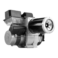
When contacting Beckett for service information
— Please record the burner serial number (and
have available when calling or writing). You will
fi nd the serial number on the silver label located
on the left rear of the burner. Refer to Figure 1.
Inspect/Prepare Installation Site
Clearances to Burner and Appliance
Provide space around burner and appliance for
ease of service and maintenance. Check the
minimum clearances against those shown by the
appliance manufacturer and by applicable building
codes.
Inspect Chimney or Direct Vent System
•
•
•
 Loading...