Page 16 RWB 6104 WMNX
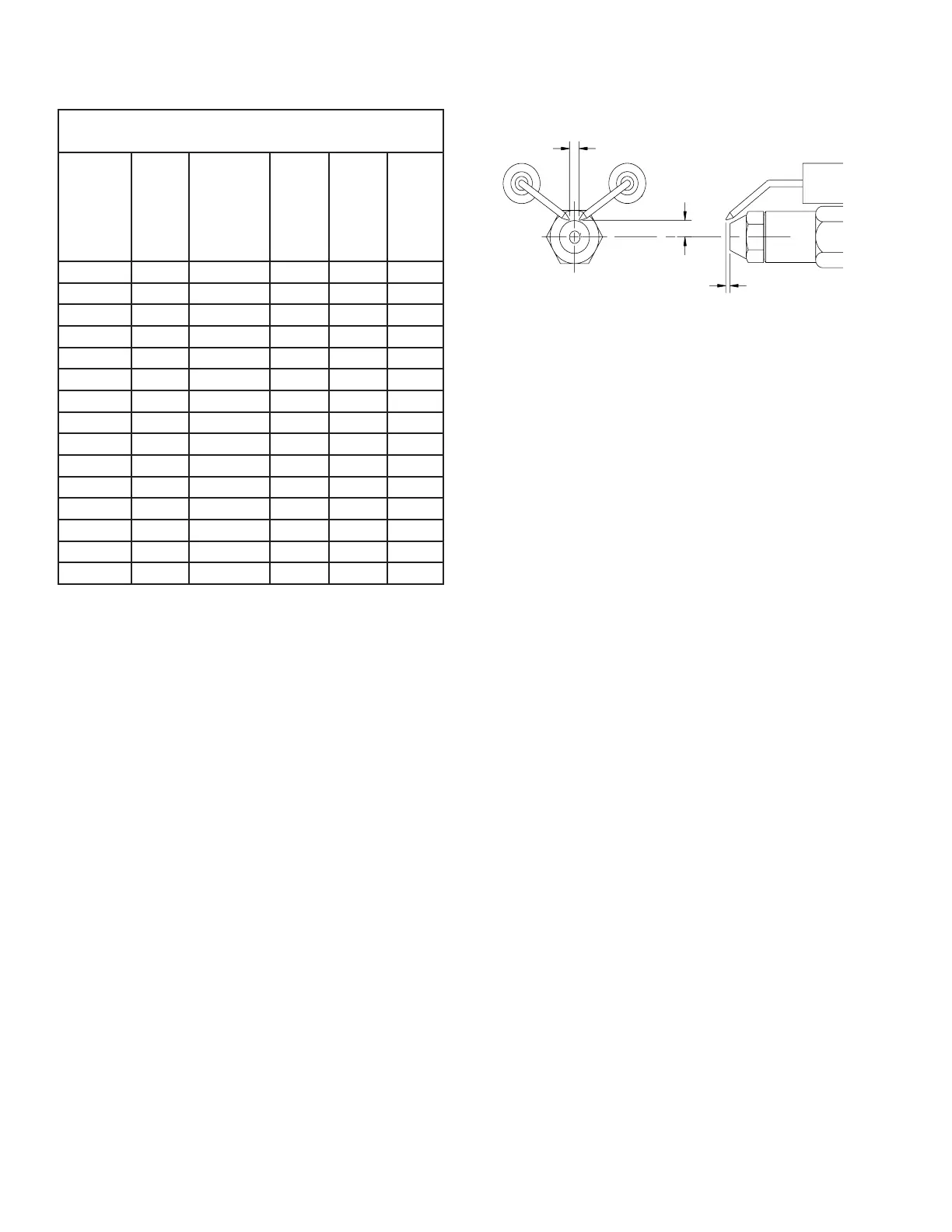
5/32” GAP
1/4” above
nozzle center
3/32” Nozzle-to-tip
Spacing
SK9664
Nozzle fl ow rate U. S. gallons per hour of No. 2 fuel oil when
pump pressure (psig) is:
Nozzle
size
(rated
at 100
psig)
125
psi
140 psi
(factory
std.)
150
psi
175
psi
200
psi
0.40 0.45 0.47 0.49 0.53 0.56
0.50 0.56 0.59 0.61 0.66 0.71
0.60 0.67 0.71 0.74 0.79 0.85
0.65 0.73 0.77 0.80 0.86 0.92
0.75 0.84 0.89 0.92 0.99 1.06
0.85 0.95 1.01 1.04 1.13 1.20
0.90 1.01 1.07 1.10 1.19 1.27
1.00 1.12 1.18 1.23 1.32 1.41
1.10 1.23 1.30 1.35 1.46 1.56
1.20 1.34 1.42 1.47 1.59 1.70
1.25 1.39 1.48 1.53 1.65 1.77
1.35 1.51 1.60 1.65 1.79 -
1.50 1.68 1.77 1.84 - -
1.65 1.84 - - - -
1.75 -----
Nozzle Flow Rate by Size
Figure 12. – Electrode tip gap and spacing
Trained Service Technician’s Regular Maintenance
Note that if the throttle cup is moved be sure to re-
position it with no gap between the nozzle adapter
and hub.
Check Retention Head Alignment and
Cad Cell Sighting
(Refer to Figure 13.)
The cad cell sighting holes in the throttle cup
and the retention head must be aligned to allow
the cad cell to detect the fl ame. Make sure the
stamped key in the retention head collar lines
up with the keyway in the nozzle adapter when
mounting the retention head. Note that in specifi c
applications, the retention head may not have a
sighting hole.
Check/Adjust “Zero” Calibration
On burners with factory-installed air tubes, the
zero calibration has been factory set. Make sure
the retention head (Figure 10) is securely against
the stops in the retention ring when the adjustment
plate pointer is at “0” (Figure 9).
If the zero calibration has not been set, perform
the following procedure:
Install the nozzle line, with the adjustment plate
assembly attached, into the burner.
Install and tighten the rear door to hold the air
adjustment plate assembly in position.
Slightly loosen the upper acorn nut, the splined
nut, and the lower acorn nut.
Turn the air adjustment screw clockwise to
adjust the plate with the pointer to the zero posi-
tion.
Referring to Figure 10, slide the nozzle line as-
sembly forward until the retention head engages
the fi xed stops in the retention ring at the end of
the air tube.
Tighten the upper acorn nut securely.
•
•
1.
2.
3.
4.
5.
6.
To install a new nozzle, place a 3/4” open-end
wrench on the nozzle adapter. Insert the nozzle
into the adapter and secure fi nger tight. Finish
tightening with a 5/8” open-end wrench. Use
care to avoid bending the burner head support
legs or electrodes.
Do not over-torque the nozzle when install-
ing. This will cause deep grooves in the nozzle
adapter, preventing a seal when a new nozzle is
installed.
Carefully check and realign the electrode tips
after replacing a nozzle, ensuring the electrode
settings comply with Figure 12.
If the head was removed when replacing the
nozzle, carefully reconnect the head to the
nozzle adapter. Make sure to align the key in
the support leg with the keyway in the nozzle
adapter and to butt the head support to the
nozzle adapter shoulder, see Figure 10.
Check/Adjust Electrodes
Check the electrode tip settings, as shown in
Figure 12. If necessary, adjust by loosening the
electrode clamp screw (Figure 10) and slide/rotate
the electrodes as necessary. When the adjustment
is complete, securely tighten the clamp screw.
7.
8.
9.
10.
•
 Loading...