RWB 6104 WMNX Page 9
Verify that the air tube installed on the burner
provides the correct insertion depth. See
Figure 4.
The end of the air tube should normally be ¼”
back from the inside wall of the combustion
chamber. Never allow the leading edge of the
head assembly to extend into the chamber,
unless otherwise specifi ed by the heating
appliance manufacturer. Carefully measure
the insertion depth when using an adjustable
fl ange. Verify the insertion depth when using a
welded fl ange.
Installing the Oil Tank and Supply Sys-
tem
2.
3.
•
Note: to determine the proper fuel line size, refer
to the fuel pump manufacturer’s instructions pro-
vided with the burner. Refer to Figure 5 or Figure 6
for typical installation layouts.
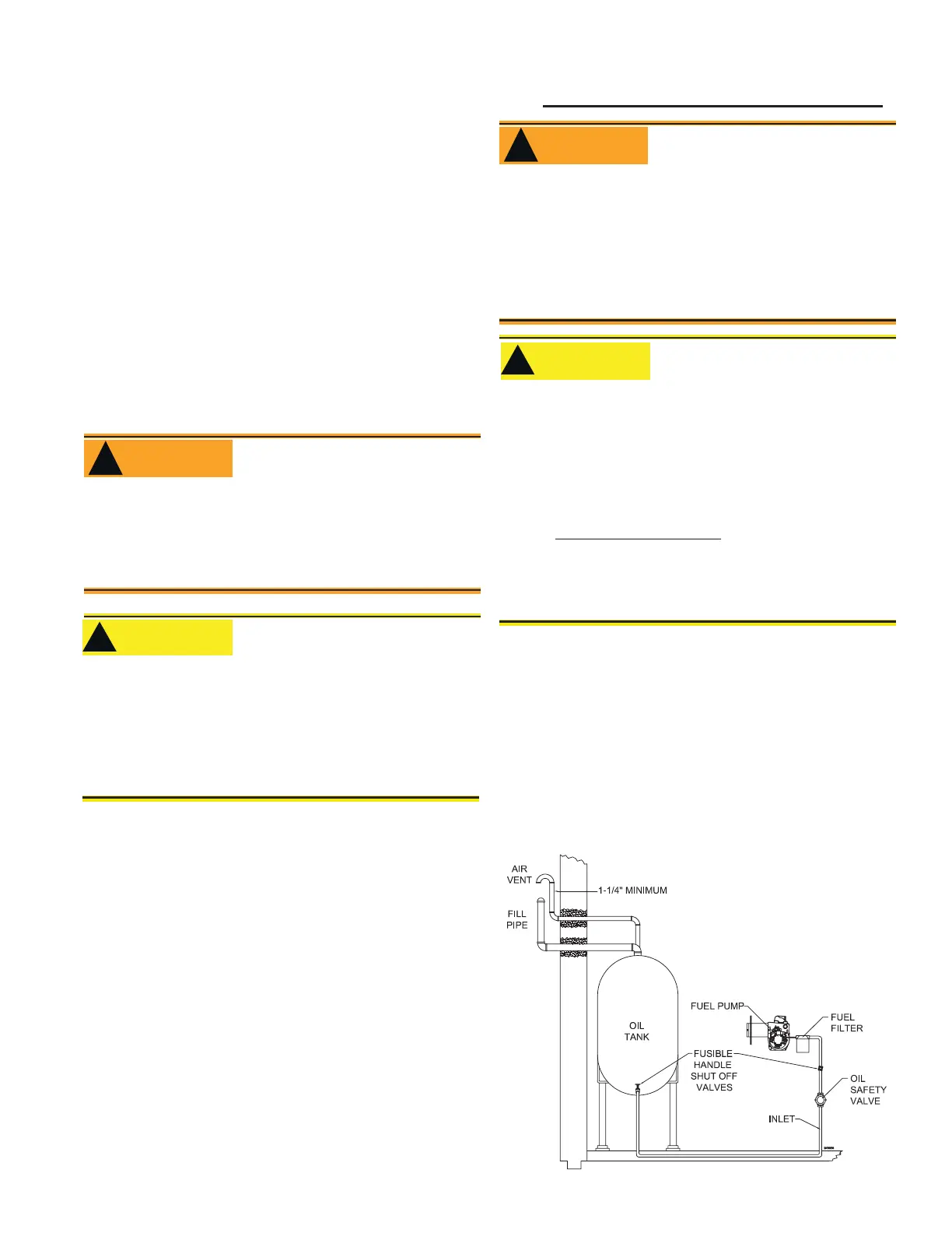
Fuel Line Valves and Filter
Install two high quality, oil duty rated, fusible
handle design shutoff valves in accessible loca-
tions on the oil supply line. Locate one close to the
tank and the other close to the burner, upstream of
the fi lter for service access.
Install a generous capacity fi lter inside the building
between the fuel tank shutoff valve and the burner,
locating both the fi lter and the valve close to the
burner for ease of servicing. Filter should be rated
for 50 microns or less.
Fuel supply level with or above burner
•
The burner is shipped without the by-pass plug in-
stalled.
Install the by-pass plug in two-pipe oil supply systems
ONLY.
•
•
Failure to comply could cause immediate pump
seal failure, pressurized oil leakage and the po-
tential for a fi re and injury hazard.
Do Not Install By-pass Plug
with 1-Pipe System
WARNING
!
The oil supply inlet pressure to the burner cannot
exceed 3 psig.
Insure that a pressure limiting device is installed
in accordance with the latest edition of NFPA 31.
Do NOT install valves in the return line.
Gravity Feed Systems: Always install an anit-
siphon valve in the oil supply line or a solenoid
valve (RWB Part # 2182602U) in the pump/noz-
zle discharge tubing to provide backup oil fl ow
cut-off protection.
•
•
•
•
Damage to the fi lter or pump seals could cause
oil leakage and a fi re hazard.
Oil Supply Pressure
Control Required
!
CAUTION
Never use Tefl on tape on fuel oil fi ttings.
Tape fragments can lodge in fuel line components
and fuel unit, damaging the equipment and pre-
venting proper operation.
Use oil-resistant pipe sealant compounds.
•
•
•
Damage to the pump could cause impaired burn-
er operation, oil leakage and appliance soot-up.
Do Not Use Tefl on Tape
!
CAUTION
Oil Leak and Fire Hazard
WARNING
!
Install the oil tank following applicable stan-
dards in the U.S. by referring to the latest
edition of NFPA 31 or CSA-B139 & CSA-B140
in Canada, and all authorities having jurisdic-
tion.
Figure 5. – Inside Tank Gravity Feed System
The burner may be equipped with a single-stage
fuel unit for these installations. Connect the fuel
supply to the burner with a single supply line if you
want a one-pipe system (making sure the bypass
plug is NOT installed in the fuel unit.) Manual
bleeding of the fuel unit is required on initial start-
up. If connecting a two-pipe fuel supply, install the
fuel unit bypass plug.
 Loading...