Product overview
C9900-G05x14 Version: 1.0
3.3 Description of the boards
The boards used and their connectors are described and explained below. The C9900-G05x push-button
extensions are wired ex factory to a 19-pin round connector. Named plug designations (CONxxx) can be
found in the individual circuit diagrams.
NOTE
Switching voltage too high
An excessively high switching voltage can lead to damage to property.
• Supply the push-buttons with a maximum of 35 V and a maximum switching capacity per push-button of
250 mW.
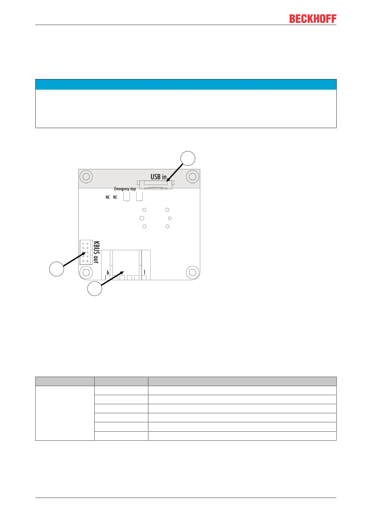
Emergency stop board for C9900-G050, C9900-G052, C9900-G054 and C9900-G056
Fig.3: A918 emergency stop board
The emergency stop board has a USB-to-KBUS coupler to control the inputs and outputs of the push-
buttons. The "USB IN" 1, CON500, is supplied from the Control Panel, the "KBUS OUT" 2, CON400, links
the other push-button boards. The two break contacts of the emergency stop are wired to the 19-pin round
connector via connection strip 3, CON402. The assignment of the connection strip is listed in the table
below.
Table7: Connection strip assignment - A918 emergency stop board
Connection strip Terminal point Description
3 1 Input break contact 1
2 Output break contact 1
3 Input break contact 2
4 Output break contact 2
5 Not used
6 Not used
3-button board for the C9900-G050 and C9900-G052 (red, green and blue push-buttons)

 Loading...