Product overview
C9900-G05x 17Version: 1.0
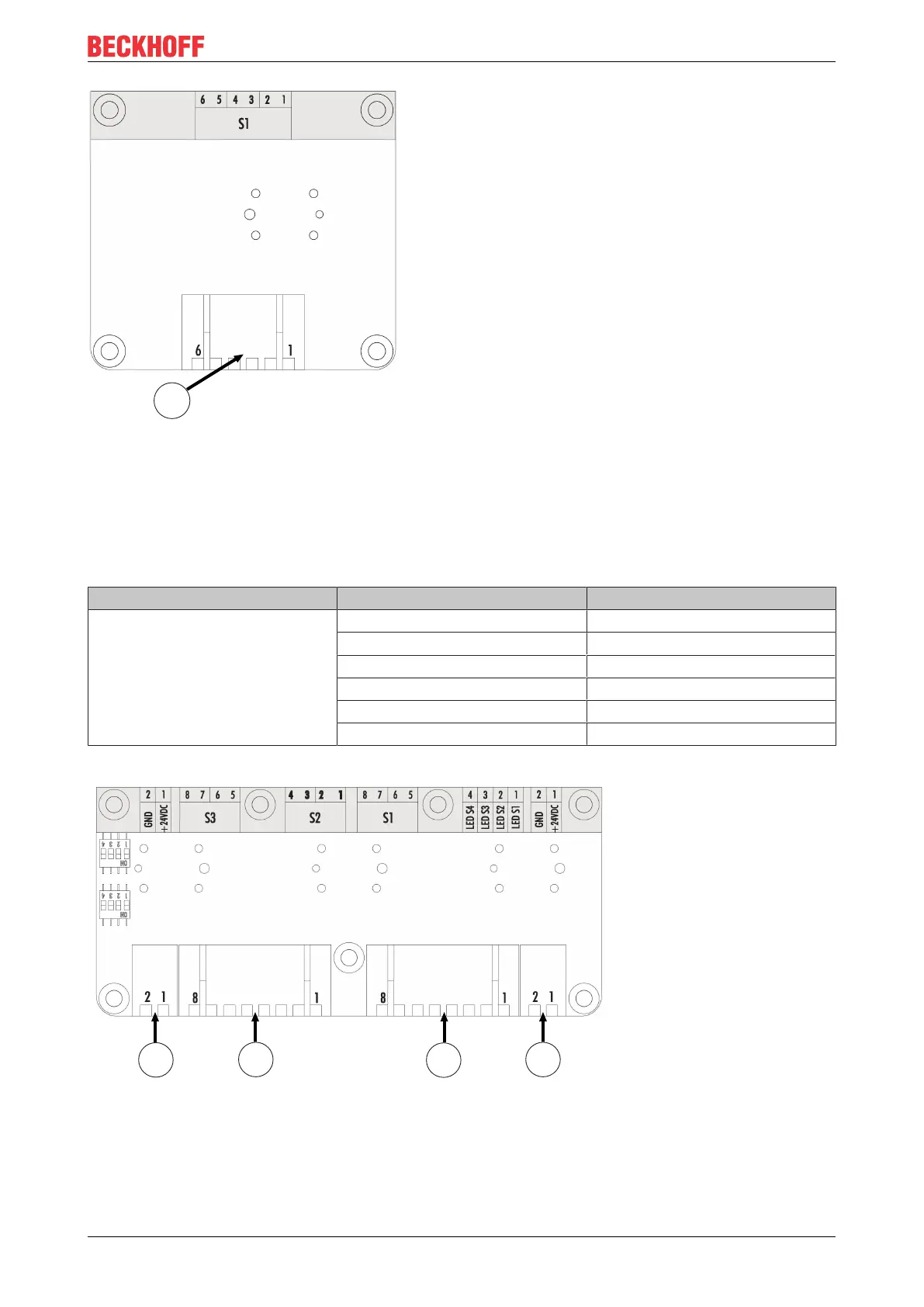
Fig.6: A971 emergency stop board
The emergency stop board has a connection strip 1, CON402, via which two break contacts of the
emergency stop are connected to the 19-pin round connector. The assignment of the connection strip is
listed in the table below.
Table10: Connection strip assignment - A971 emergency stop board
Connection strip Terminal strip Description
1 1 Input break contact 1
2 Output break contact 1
3 Input break contact 2
4 Output break contact 2
5 Input make contact 1
6 Output make contact 1
3-button board for C9900-G051 and C9900-G053
Fig.7: A972 3-button board
The 3-button board has two external connection strips 1, CON600 & CON601, which are used for the power
supply to the board. LEDs 1-3 and the push-button S1 are wired via connection strip 3, CON602. Connection
strip 2, CON603, is used for the wiring of the push-buttons S2 and S3.

 Loading...