Product overview
C9900-G05x16 Version: 1.0
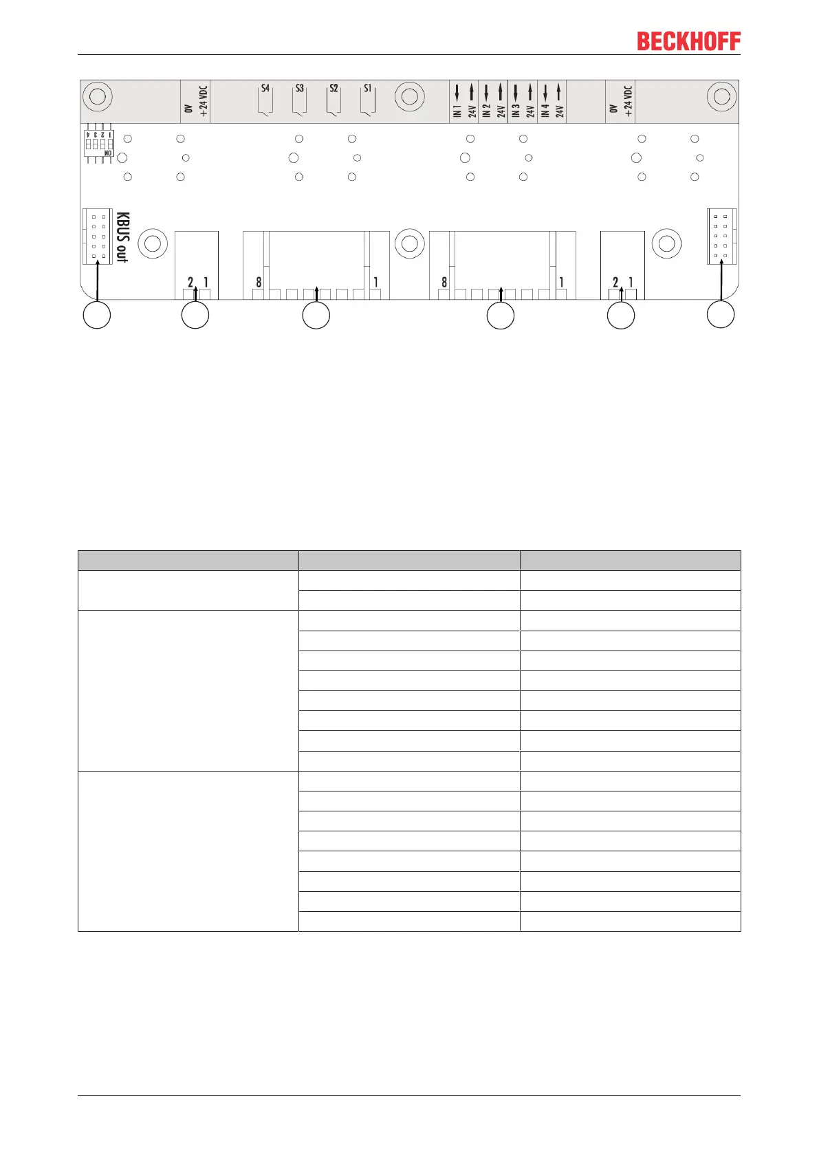
Fig.5: A920 4-button board
The 4-button board has two K-bus interfaces 1, CON400 & CON401. "KBUS IN" connects the board to the
USB-to-KBUS coupler and transmits one make contact and the LED per button. A jumper must be set on
"KBUS OUT" as the terminating resistor. The external connection strips 2, CON600 & CON601, are used to
supply power to the indicator lamps.
The second contact of each push-button is wired to the 19-pin round connector via connection strip 3,
CON603.
Four digital inputs are available on connection strip 4, CON602, which can be assigned ex factory.
Table9: Assignment of connection strip - A920 four-button board
Connection strip Terminal point Description
2 1 24 V DC
2 0 V
3 1 Input make contact 1
2 Output make contact 1
3 Input make contact 2
4 Output make contact 2
5 Input make contact 3
6 Output make contact 3
7 Input make contact 4
8 Output make contact 4
4 1 24 V output
2 Digital input 1
3 24 V output
4 Digital input 2
5 24 V output
6 Digital input 3
7 24 V output
8 Digital input 4
Emergency stop board for C9900-G051, C9900-G053, C9900-G055 and C9900-G057

 Loading...